
Software systems grow in complexity. As codebases expand, the relationships between components become intricate and difficult to navigate. Without a clear structural representation, development teams face challenges in maintaining consistency, managing dependencies, and ensuring scalability. The Unified Modeling Language (UML) offers a standardized way to visualize this architecture. Among its various diagram types, the Package Diagram stands out as a critical tool for high-level organization.
This guide explores the mechanics, strategies, and practical applications of UML Package Diagrams. We examine how these diagrams facilitate the division of complex systems into manageable units. By understanding namespaces, dependencies, and hierarchical structures, architects can create a blueprint that supports long-term evolution.
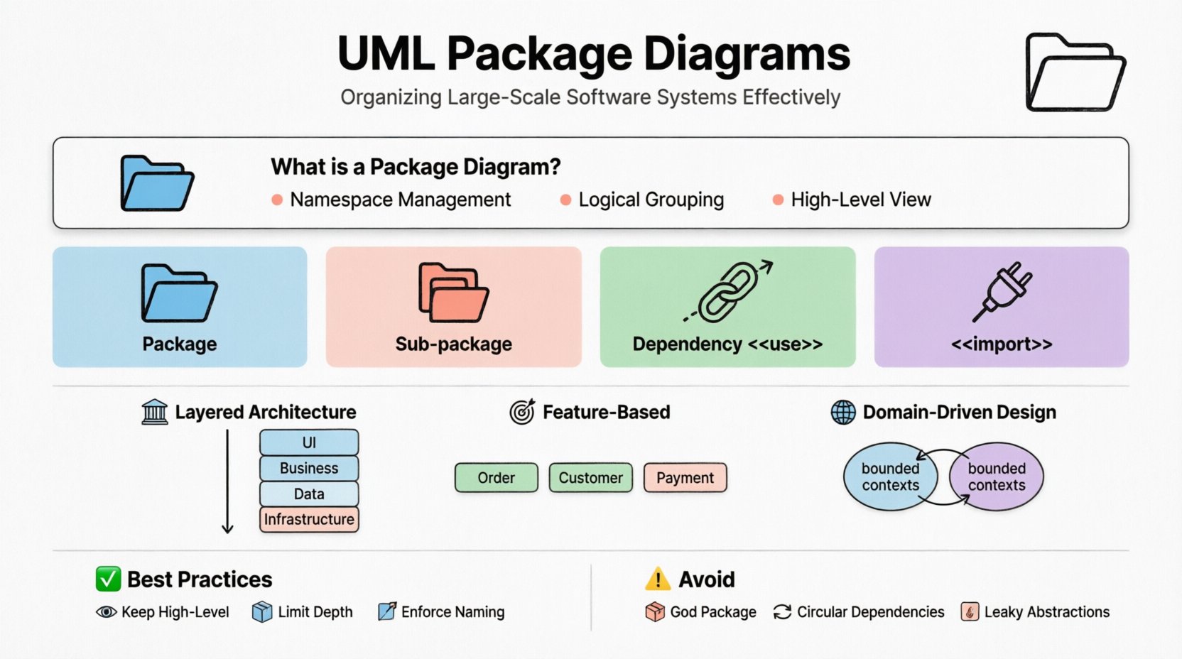
🧩 What is a Package Diagram? 📋
A Package Diagram serves as a namespace diagram. It shows the organization and dependencies among a set of packages. In the context of software engineering, a package acts as a grouping mechanism for related elements such as classes, interfaces, components, and other packages. It is the primary method for managing the cognitive load of large systems.
- Namespace Management: Packages prevent naming conflicts by isolating identifiers.
- Logical Grouping: They group features or modules that share a common responsibility.
- High-Level View: They abstract away implementation details to focus on structural relationships.
Unlike Class Diagrams, which detail specific data structures and methods, Package Diagrams operate at a macro level. They provide a map of the system’s ecosystem rather than the specific terrain. This abstraction is essential for architects who need to communicate structure to stakeholders without getting lost in implementation specifics.
⚙️ Core Notation and Syntax 🛠️
Understanding the visual language of UML is fundamental to creating effective diagrams. A package is represented by a rectangle with a small tab on the upper left. The name of the package is placed inside the rectangle, usually bolded or centered.
Standard notation includes:
- Package Icon: A folder-like tab on the top left corner of the rectangle.
- Package Name: Text placed within the main body, often preceded by the keyword <<package>> in some notations, though often omitted for clarity.
- Contents: Items contained within the package are listed below the name, separated by a dashed line.
When packages contain other packages, this creates a hierarchy. This nesting capability allows for deep organization. A top-level package might represent the entire application, while sub-packages represent modules, subsystems, or layers.
Table: Key Symbols in Package Diagrams 📊
| Symbol | Meaning | Usage Context |
|---|---|---|
| 📁 Rectangle with Tab | Package | Grouping related elements |
| 📂 Nested Rectangle | Sub-package | Hierarchical organization |
| 🔗 Dashed Arrow | Dependency | One package uses another |
| 🔒 Solid Line | Association | Structural relationship (rare in packages) |
| 🔌 <<import>> | Import | Bringing in external definitions |
🔗 Managing Dependencies and Relationships 🔄
The most critical aspect of a Package Diagram is how packages interact. Dependencies define the flow of information and control between modules. Properly modeling these relationships helps identify coupling and cohesion issues early in the design phase.
Dependency Types Explained 📝
Dependencies are directional. They indicate that the source package relies on the target package for functionality. There are specific stereotypes that clarify the nature of this reliance.
- <<use>>: Indicates that one package requires functionality from another. This is the most common dependency type.
- <<import>>: Suggests that the namespace of the target package is added to the source package.
- <<access>>: Implies direct access to elements within the target package.
- <<merge>>: Used when combining models from different sources.
- <<extend>>: Often used in use case contexts but can apply to package extensions in specific modeling tools.
Table: Dependency Relationships 📋
| Relationship | Arrow Style | Stereotype | Implication |
|---|---|---|---|
| Dependency | Dashed Open Arrow | <<use>> | Client needs Server |
| Import | Dashed Open Arrow | <<import>> | Public interface exposed |
| Realization | Dashed Open Arrow | <<realize>> | Implementation of contract |
| Generalization | Solid Line with Hollow Arrow | None | Inheritance of package structure |
When modeling large systems, minimize the number of dependencies crossing package boundaries. High coupling between packages makes the system rigid and difficult to modify. A change in one package should ideally not ripple through the entire architecture.
🏗️ Hierarchical Organization Strategies 📚
Effective organization relies on a logical hierarchy. There is no single correct way to structure packages, but certain patterns are widely adopted in the industry. These patterns help teams align their mental models with the physical codebase.
Layered Architecture 🏛️
In a layered approach, packages are organized by abstraction level. This is common in enterprise applications.
- UI Layer: Handles presentation and user interaction.
- Business Logic Layer: Contains core rules and processes.
- Data Access Layer: Manages persistence and database communication.
- Infrastructure Layer: Deals with networking, security, and system resources.
Dependencies typically flow downward. The UI layer depends on Business Logic, which depends on Data Access. The Infrastructure layer sits at the bottom, supporting all others. This prevents lower-level details from leaking into higher-level concerns.
Feature-Based Organization 🎯
For systems driven by business functionality, organizing by feature is often more intuitive.
- Order Management Package: Contains all classes related to placing and tracking orders.
- Customer Portal Package: Handles user registration and profile management.
- Payment Gateway Package: Manages transaction processing.
This approach supports modular development, where teams can work on specific features with minimal interference. It aligns well with microservice architectures where boundaries are clear.
Domain-Driven Design (DDD) 🌐
DDD suggests organizing packages around business domains. Each domain represents a specific area of business expertise.
- Bounded Contexts: Distinct packages representing different models of the same concept.
- Aggregates: Groups of related objects treated as a single unit.
- Entities: Objects defined by their identity rather than attributes.
Using DDD principles in Package Diagrams ensures that the software structure reflects the business reality. This makes the system easier to understand for both developers and business analysts.
💡 Best Practices for Scalability 🚀
Creating a diagram is one step; maintaining it is another. As the system evolves, the diagram must evolve with it. Following best practices ensures the documentation remains relevant and useful.
- Keep It High-Level: Do not list every class in a package diagram. Use summary notes or drill down to a Class Diagram for details.
- Limit Package Depth: Avoid nesting more than three or four levels deep. Deep hierarchies become confusing to navigate.
- Enforce Naming Conventions: Use consistent naming for packages. Prefixes like
com.company.modulehelp in identification. - Define Interfaces: Clearly mark which elements are exported. Internal packages should not leak implementation details.
- Review Regularly: Schedule reviews during sprint planning or architecture meetings to ensure alignment.
Scalability also involves managing the volume of dependencies. If a package has more than ten incoming dependencies, it may be doing too much. Refactoring to split responsibilities can reduce complexity.
⚠️ Common Pitfalls and Anti-Patterns 🚫
Even experienced architects make mistakes. Recognizing these patterns helps in avoiding structural debt.
- The God Package: A single package that contains everything. This creates a bottleneck and high coupling.
- Circular Dependencies: Package A depends on Package B, and Package B depends on Package A. This creates a deadlock in compilation or execution.
- Leaky Abstractions: Allowing internal implementation details to be visible outside the package boundary.
- Over-Granularity: Creating too many small packages. This increases the overhead of managing imports and exports.
- Ignoring Physical Constraints: Designing packages that do not align with deployment units or file system structures.
Circular dependencies are particularly dangerous. They make it difficult to build or test individual components. Tools can detect these cycles, but manual review is often necessary to understand the business justification for the link.
🔗 Integration with Other UML Diagrams 🧩
Package Diagrams do not exist in isolation. They connect with other views of the system to provide a complete picture.
Class Diagrams 📄
Class Diagrams provide the detail within a Package. A Package Diagram shows the relationship between modules, while the Class Diagram shows the classes inside those modules. The package boundary in the Package Diagram corresponds to the namespace in the Class Diagram.
Component Diagrams 🧱
Component Diagrams are similar but focus on runtime artifacts. Packages are often mapped to components during deployment. A package might represent a logical unit, while a component represents a deployable unit like a JAR or DLL.
Deployment Diagrams 🖥️
Deployment Diagrams show where components are placed in the infrastructure. Packages help organize the software that runs on the nodes. Understanding the package structure aids in determining how to distribute services across servers.
Sequence Diagrams 💬
Sequence Diagrams illustrate interactions over time. When drawing interactions, it is helpful to label objects with their package name. This reinforces the structural boundaries and shows which modules are communicating.
🔄 Maintenance and Evolution 📈
Software is never static. Requirements change, and new technologies emerge. The package structure must adapt. This requires a disciplined approach to refactoring.
Refactoring Steps:
- Identify Boundaries: Determine where current packages are too loose or too tight.
- Move Elements: Shift classes or interfaces to new packages that better fit the new design.
- Update Dependencies: Adjust the arrows and relationships in the diagram to reflect the moves.
- Verify Consistency: Ensure that all imported names are valid and no broken links exist.
Automation plays a role here. Many modeling tools allow for code generation and reverse engineering. If the code structure changes, the model can be synchronized to reflect reality. However, manual oversight is still required to ensure the logical grouping makes sense.
🛡️ Security and Access Control 🔒
Packages can also model security boundaries. In some systems, access to certain packages is restricted based on user roles or network location.
- Internal Packages: Marked as private. Only accessible within the same module.
- Public Packages: Exposed via interfaces. Accessible by external systems.
- Protected Packages: Accessible only by trusted subclasses or modules.
Documenting these access levels in the Package Diagram helps security teams audit the system. It ensures that sensitive data flows are not inadvertently exposed to unauthorized modules.
📝 Final Considerations for Architects 👨💻
Building a robust architecture requires more than just drawing boxes and arrows. It demands a deep understanding of the domain, the technology stack, and the team’s workflow. Package Diagrams are a communication tool as much as they are a design tool.
When presenting these diagrams to stakeholders, focus on the value they provide. Explain how the structure reduces risk, improves maintainability, and facilitates parallel development. Avoid getting bogged down in syntax unless the audience is technical.
Remember that the diagram is a living document. It should be updated whenever the system changes significantly. Outdated diagrams are worse than no diagrams, as they mislead the team. Treat the model as a contract between the design and the implementation.
By adhering to these principles, teams can create systems that are not only functional but also adaptable. The effort invested in organizing packages pays dividends in the form of reduced technical debt and faster delivery cycles. Structure is the foundation of stability.