
Software architecture relies heavily on clear communication between stakeholders, developers, and analysts. At the heart of this communication lies the Unified Modeling Language, specifically the Use Case Diagram. These diagrams provide a high-level view of how users interact with a system. However, despite their simplicity in appearance, creating accurate UML use case diagrams requires precision. Many teams struggle with structural integrity, leading to confusion during the implementation phase.
When a diagram is ambiguous, the code built upon it often becomes flawed. Misunderstandings regarding boundaries, actors, or relationships can cascade into significant technical debt. This guide addresses the most frequent errors encountered during the modeling process. By identifying these pitfalls early, you can ensure your requirements specification remains robust and actionable.
Why Precision Matters in Use Case Modeling 🎯
A use case diagram is not merely a drawing exercise; it is a contract. It defines the scope of functionality from the perspective of the external entities interacting with the system. If the diagram fails to capture the true intent, the resulting software will likely miss critical requirements or include unnecessary features.
Proper modeling ensures that:
- Stakeholders agree on what the system does and does not do.
- Developers understand the entry and exit points for every feature.
- Testers have clear criteria for validation scenarios.
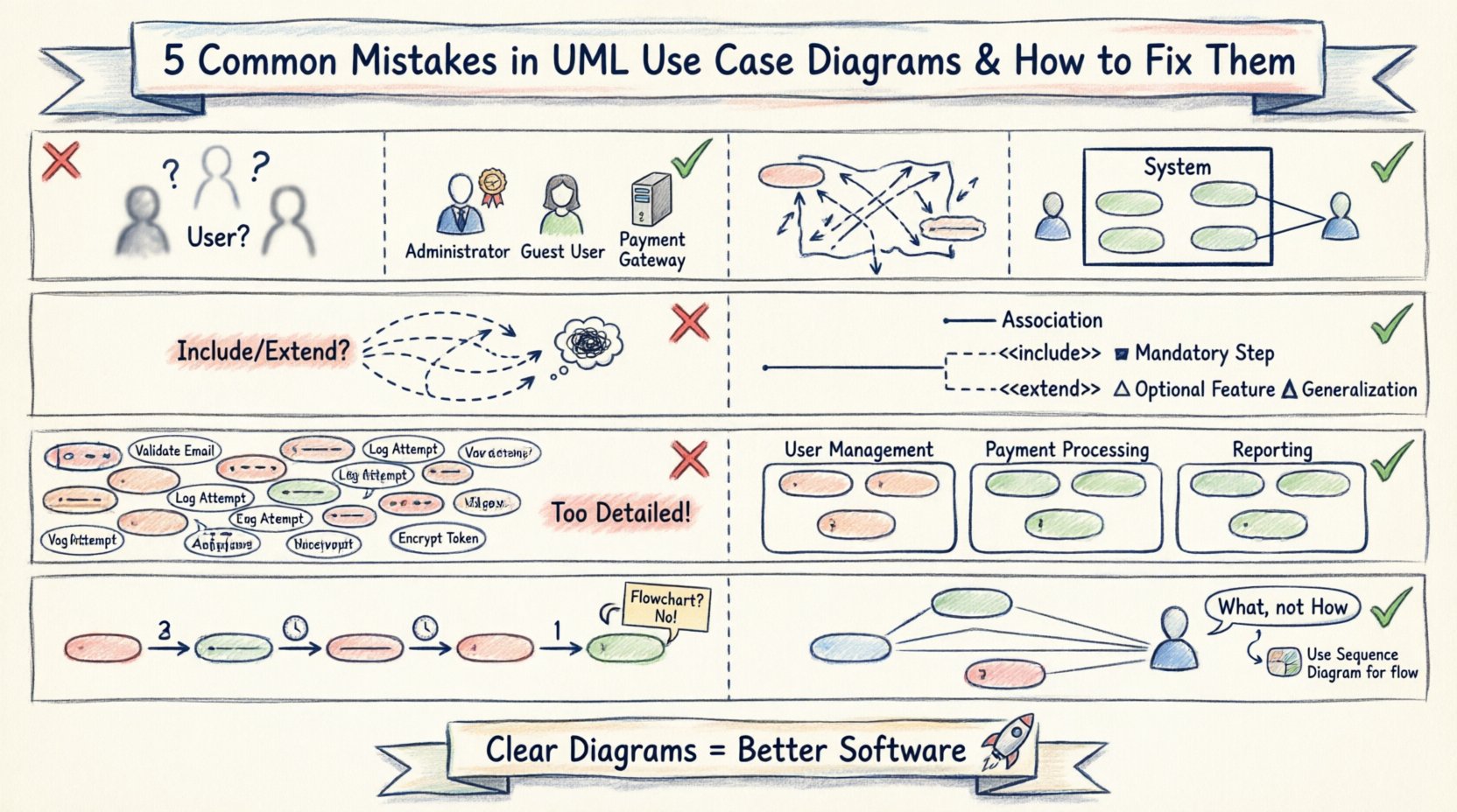
Below, we explore five specific mistakes that compromise this clarity and provide actionable corrections to restore diagram integrity.
Mistake 1: Ambiguous or Overlapping Actor Definitions 🧑💼
One of the most prevalent issues in use case modeling is the definition of actors. An actor represents a role played by a user or an external system that interacts with the subject. The problem arises when roles are defined too broadly or when specific user types are conflated.
The Problem
Designers often create a single actor named “User.” This is insufficient because a “User” could be an administrator, a customer, or a guest, each having vastly different permissions and capabilities. Using a generic label forces the team to rely on notes or text descriptions to explain permissions, cluttering the diagram and reducing readability.
Another common error is creating too many specific actors. If you define “John” and “Jane” as separate actors, you have lost the abstraction required for a use case diagram. Actors should represent roles, not specific individuals.
The Fix
To resolve this, adhere to the following principles:
- Identify Roles, Not People: Rename generic actors to specific roles like Administrator, Guest User, or Payment Gateway.
- Use Generalization: If multiple roles share the same behaviors, use inheritance. For example, if both Admin and Editor can create content, they can both extend a parent role like Content Contributor.
- Define External Systems: Do not forget that other software systems can be actors. If your application sends data to an external API, that API is an actor.
By clearly distinguishing roles, the diagram immediately communicates who is allowed to perform specific actions without needing additional documentation.
Mistake 2: Ignoring the System Boundary 🧱
The system boundary is the rectangle that encloses all use cases. It defines the scope of the software being modeled. Everything outside the box is external; everything inside is part of the system under construction. Many diagrams fail to draw this boundary clearly or include elements that should be outside.
The Problem
When the boundary is vague, it becomes unclear which functionality belongs to the current project and which belongs to legacy systems or third-party services. A common mistake is drawing use cases inside the box that are actually performed by the actor. For instance, “Click Login Button” is an action performed by the user, not a function of the system. The system function is “Authenticate User”.
Conversely, some modelers place too much detail inside the boundary. A use case diagram should remain high-level. Listing every validation step or database query inside a use case bubble violates the purpose of the diagram.
The Fix
Strictly enforce the definition of the system boundary:
- Encapsulate System Functions: Only place actions initiated or controlled by the software inside the rectangle.
- Exclude User Actions: Actions like “Type Password” or “Click Submit” belong to the actor’s side of the interaction, not the system’s use case.
- Clarify Scope: If a feature is being phased out or is handled by a legacy system, draw the boundary to explicitly exclude it or place it outside the box with a clear association.
This distinction prevents scope creep during development. Developers will know exactly what they are responsible for building versus what they are integrating.
Mistake 3: Misusing Relationships (Include vs. Extend) 🔄
UML defines specific relationship types to show how use cases interact. The most frequently confused are the Include and Extend relationships. Using them interchangeably creates logical errors in the requirement specification.
The Problem
Many diagrams treat Include and Extend as synonyms for “linked” or “related.” This leads to ambiguity about when a function is mandatory versus when it is optional.
- Include: Indicates that the base use case requires the included use case to complete. It is mandatory behavior.
- Extend: Indicates that the extending use case adds optional behavior to the base use case under specific conditions.
If you use Include for an optional feature, the system will be forced to execute it every time, violating user expectations. If you use Extend for a mandatory step, developers might skip it, breaking the core functionality.
The Fix
Apply these rules to maintain logical consistency:
- Use Include for Mandatory Steps: If every time a user logs in, they must verify their email, that verification is an Include.
- Use Extend for Optional Variations: If a user can choose to save their session for future logins, that is an Extend. It does not happen every time.
- Limit Depth: Avoid chaining Include relationships too deeply (e.g., Use Case A includes B, which includes C, which includes D). This creates a spaghetti-like dependency that is hard to trace.
Understanding the conditional logic behind these arrows is crucial for writing accurate test cases later in the lifecycle.
Mistake 4: Poor Granularity and Clutter 📉
Use case diagrams are meant to be at a high level of abstraction. A common mistake is over-complicating the diagram by breaking down use cases into sub-steps that belong in sequence diagrams or activity diagrams.
The Problem
When a diagram becomes too busy, stakeholders lose the ability to see the forest for the trees. A single use case should represent a complete unit of functionality that delivers value to an actor. If a use case requires ten steps to complete, it might be too granular.
However, if a use case is too vague, it becomes useless. The balance is difficult to strike. Drawing 50 use cases on one screen makes the diagram unreadable. Conversely, drawing only two use cases for a complex system suggests a lack of understanding of the requirements.
The Fix
Manage complexity through structured decomposition:
- Group by Actor: If an actor has too many use cases, consider grouping them into subsystems or separate diagrams based on functional modules.
- Abstract Details: If a use case like “Process Order” involves complex internal logic, do not draw the steps. Let the Use Case name imply the action. Use other diagrams for the flow.
- Avoid Redundancy: If multiple actors perform the same use case, do not draw the use case multiple times. Draw it once and link it to all relevant actors.
A clean diagram reduces cognitive load for everyone reviewing the requirements.
Mistake 5: Confusing Use Cases with Process Flows 📉
This is a conceptual error where the diagram attempts to show the sequence of events rather than the functional capabilities. A use case diagram is static; it describes what the system can do, not how it does it step-by-step.
The Problem
Modelers often draw arrows between use cases to indicate the order of execution. For example, they might draw an arrow from “Login” to “View Dashboard” implying that “View Dashboard” must happen immediately after “Login.” While there is a logical flow, the diagram does not enforce sequence. This confuses developers who expect a sequence diagram for flow control.
Another aspect of this mistake is treating the diagram as a flowchart. Arrows should only represent associations (interaction) or dependencies (include/extend), not the chronological order of a transaction.
The Fix
Separate concerns between different diagram types:
- Use Sequence Diagrams for Flow: If you need to show the order of messages between actors and the system, use a Sequence Diagram.
- Keep Associations Pure: Use solid lines only to show that an actor interacts with a use case. Do not add arrowheads to associations unless they represent a specific relationship type like Generalization.
- Focus on Value: Ask “What value does this use case provide to the actor?” If the answer is a step in a process, ensure the use case encapsulates the entire value exchange.
Respecting the static nature of the use case diagram preserves its utility as a requirements tool.
Comparison of Relationship Types for Clarity 📊
To ensure you apply the correct logic when connecting elements, refer to the table below. This comparison highlights the functional differences between the relationship types used in UML.
| Relationship Type | Symbol | Meaning | Usage Scenario |
|---|---|---|---|
| Association | Line | Actor interacts with Use Case | Any time an actor performs an action. |
| Include | Dashed Line + <<include>> | Mandatory behavior | Base use case cannot complete without this sub-function. |
| Extend | Dashed Line + <<extend>> | Optional behavior | Base use case works without this, but it adds value under specific conditions. |
| Generalization | Triangle Arrow | Inheritance | Actor inherits capabilities from a parent role or Use Case inherits behavior. |
Implementing the Fixes: A Step-by-Step Approach 🛠️
Once you have identified the mistakes in your current diagrams, applying the corrections requires a systematic review process. Do not try to fix everything at once. Follow this workflow to sanitize your models.
Step 1: Inventory the Actors
List every actor currently on the diagram. Ask yourself if each one is a distinct role. If two actors are essentially the same, merge them. If one actor is too specific, generalize it.
Step 2: Audit the Boundaries
Draw a new box around the system. Move every use case inside that strictly belongs to the system. Move any actor actions outside. Ensure external systems are clearly labeled as actors outside the box.
Step 3: Validate Relationships
Review every dashed line. Does it represent a mandatory dependency (Include) or an optional one (Extend)? If you are unsure, assume Include is safer for core functionality, but document the conditionality in the text notes if necessary. Remove any arrows that imply sequence.
Step 4: Simplify the View
If the diagram is crowded, split it. Create a “System Overview” diagram with high-level use cases. Create detailed diagrams for specific subsystems (e.g., “Payment Processing,” “User Management”). This reduces cognitive load.
The Impact of Correct Modeling on Development 🚀
Correcting these mistakes does more than make a pretty diagram. It directly influences the quality of the software delivered.
- Reduced Rework: Clear boundaries mean developers do not waste time building features that were not in scope.
- Better Testing: Precise relationships allow QA teams to generate test suites that cover both mandatory flows (Include) and edge cases (Extend).
- Clearer Communication: When stakeholders see distinct actor roles, they can immediately identify if permissions are being granted correctly.
- Scalability: A well-structured model is easier to update when new requirements are added. You can insert new actors or extend existing use cases without breaking the whole diagram.
The cost of fixing a diagram during the requirements phase is negligible compared to the cost of fixing code after deployment. Investing time in these structural corrections pays dividends throughout the entire software development lifecycle.
Final Thoughts on Diagram Integrity ✅
A UML use case diagram is a tool for thinking, not just a tool for documentation. When you draw it correctly, you clarify your own understanding of the system. When you draw it incorrectly, you obscure the requirements and set the project up for failure.
By avoiding ambiguous actors, respecting system boundaries, utilizing relationships correctly, managing granularity, and distinguishing static models from dynamic flows, you ensure that your architecture stands on a solid foundation. Regular reviews of these diagrams against the evolving requirements will keep the model accurate as the project matures.
Focus on clarity, precision, and the specific needs of the stakeholders involved. With these practices in place, your modeling efforts will translate directly into successful software delivery.