
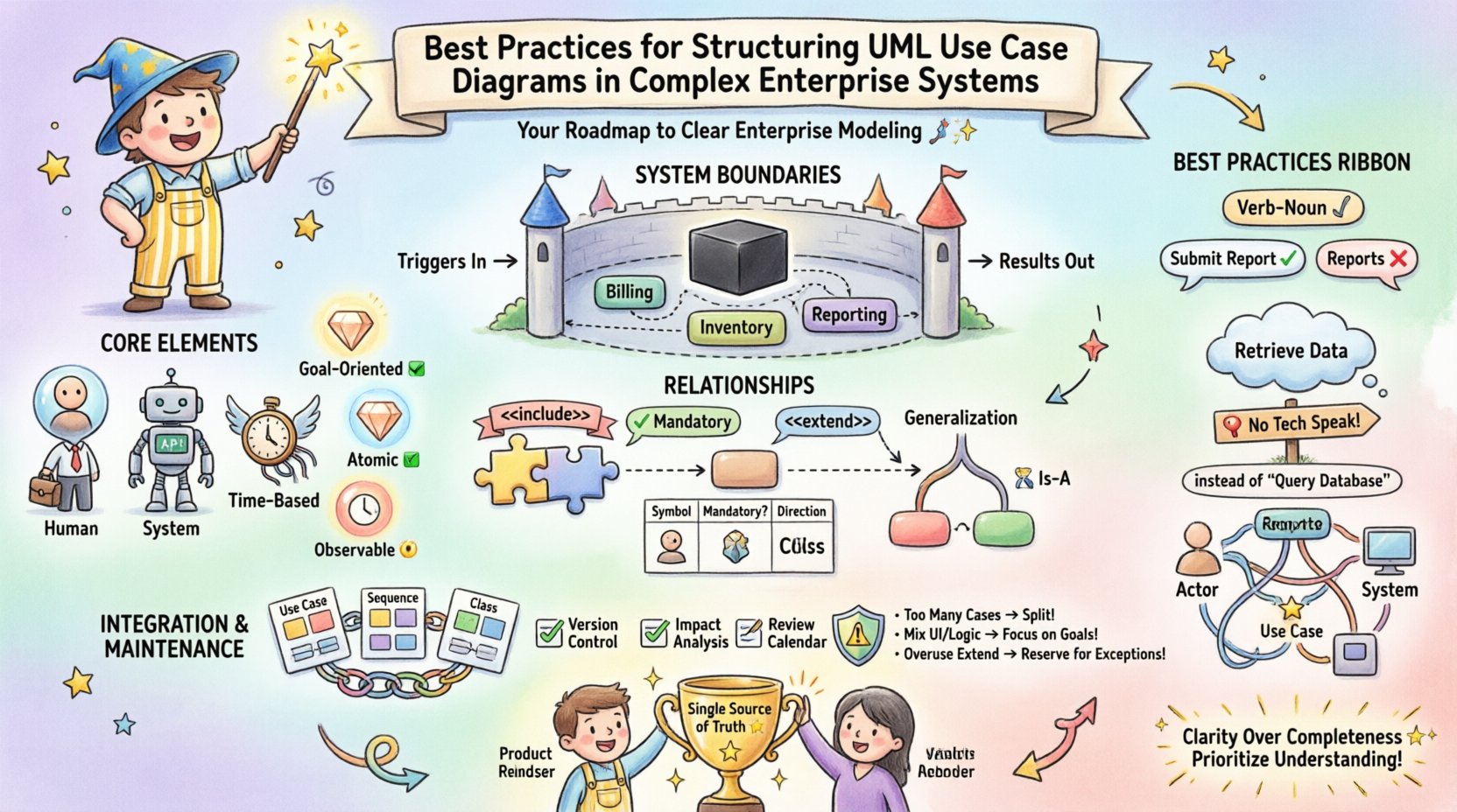
Designing software for enterprise environments presents a unique set of challenges that go far beyond simple application development. When dealing with complex enterprise systems, the architecture must support scalability, security, and interoperability across various departments and legacy platforms. One of the most critical tools in the architect’s toolkit for communicating this complexity is the Unified Modeling Language (UML) Use Case Diagram. 📊
However, a use case diagram is not merely a drawing of stick figures and ovals. In a large-scale environment, it serves as a foundational contract between business stakeholders and technical teams. It defines the scope of functionality without dictating implementation details. When structured poorly, these diagrams become cluttered, ambiguous, and ultimately useless for guiding development. When structured correctly, they provide a clear roadmap for feature implementation and system behavior. This guide explores the rigorous standards required to structure UML Use Case Diagrams effectively within complex enterprise contexts. 🚀
🧩 Understanding the Core Elements in an Enterprise Context
Before diving into structural best practices, it is essential to revisit the fundamental building blocks. In an enterprise setting, the definitions of these blocks often expand beyond their basic UML specifications.
1. Actors: More Than Just People 👥
In simple applications, actors are often human users. In enterprise systems, the actor definition must be broader to encompass the entire ecosystem. An actor represents any entity external to the system boundary that interacts with the system.
- Human Actors: End users, administrators, auditors, and support staff.
- System Actors: External APIs, third-party services, or other enterprise applications interacting via integration points.
- Time-Based Actors: Scheduled jobs, batch processes, or timers that trigger specific functions without human intervention.
When modeling complex systems, it is vital to distinguish between these types. A human actor might require a graphical interface, whereas a system actor interacts through data protocols. Confusing these can lead to architectural errors in how authentication and data exchange are handled.
2. Use Cases: Functional Units 🛠️
A use case represents a specific goal or task that an actor wishes to achieve. In enterprise modeling, granularity is key. A use case should not be too broad (e.g., “Manage System”) nor too narrow (e.g., “Click Submit Button”). It should represent a complete unit of value delivery.
- Goal-Oriented: Does this use case achieve a specific business outcome?
- Atomic: Can it be understood independently of the internal code logic?
- Observable: Does the actor perceive a change in state or a result?
🚧 Defining and Managing System Boundaries
The system boundary is the most critical structural element in a complex enterprise diagram. It draws the line between what the system does and what the environment does. In large organizations, multiple systems often exist. Clear boundaries prevent scope creep and integration confusion.
1. The Black Box Principle 🌑
Use Case Diagrams should treat the system as a black box. Internal processes, database schemas, and server configurations are irrelevant to the diagram’s purpose. The focus must remain strictly on input (triggers from actors) and output (results).
When structuring diagrams for enterprise systems, avoid including internal workflow steps as use cases. These belong in Sequence Diagrams or Activity Diagrams. Keeping the Use Case Diagram clean ensures it remains a high-level scope document.
2. Handling Subsystems and Modules 📦
As systems grow, a single diagram often becomes too crowded. This is where the concept of subsystems or packages comes into play. Rather than creating a dozen separate diagrams for every module, consider grouping related use cases into logical clusters.
- Functional Packages: Group by business domain (e.g., “Billing”, “Inventory”, “Reporting”).
- Technical Packages: Group by technical layer (e.g., “Data Access”, “Security”, “Notification Services”).
When using packages, ensure that the external actors can still be clearly associated with the specific packages they interact with. This maintains the traceability between the user’s goal and the system module responsible for it.
🔗 Mastering Relationships: Include, Extend, and Generalize
The relationships between use cases dictate the behavior flow. Misusing these relationships is a common source of documentation failure in enterprise projects. Each relationship serves a distinct semantic purpose.
1. The Include Relationship (<>) 📎
An include relationship indicates that the base use case incorporates the behavior of the included use case. It is mandatory. If you want to perform the base task, you must perform the included task.
- Use Case: “Place Order”
includes“Validate Payment”. - Reasoning: You cannot complete an order without validating payment. This logic is reused across multiple use cases (e.g., “Place Order”, “Renew Subscription”).
- Best Practice: Extract common functionality to reduce redundancy. If a behavior appears in three different use cases, make it an included use case.
2. The Extend Relationship (<>) 🔌
An extend relationship indicates optional behavior. The extending use case adds functionality to the base use case under specific conditions. It is not mandatory for the base use case to complete.
- Use Case: “View Order”
extends“Print Shipping Label”. - Reasoning: A user can view an order without printing a label. Printing is an optional extension triggered by specific conditions.
- Best Practice: Use this for error handling, alternative flows, or optional features that do not disrupt the main success path.
3. The Generalize Relationship (Generalization) 🧬
Generalization represents an inheritance relationship. One use case is a specialized version of another. This is often used for actor inheritance but applies to use cases as well.
- Actor Inheritance: “Manager” generalizes “Employee”. The Manager inherits all Employee use cases but adds specific ones.
- Use Case Inheritance: “Pay with Credit Card” generalizes “Make Payment”.
In complex systems, use case generalization can become confusing if overused. Limit it to clear hierarchies where the specialized version is strictly a subset of the general version.
📊 Comparison of Relationship Types
| Relationship Type | Symbol | Mandatory? | Direction of Dependency | Primary Use Case |
|---|---|---|---|---|
| Include | ⟶<<include>> | Yes | Base → Included | Reusing common steps |
| Extend | ⟶<<extend>> | No | Extending → Base | Optional or conditional behavior |
| Generalization | ⟶(Solid Line) | N/A | Child → Parent | Inheriting behavior (Is-A relationship) |
🔤 Naming Conventions and Semantics
In an enterprise environment, hundreds of diagrams may be created over the lifecycle of a product. Consistency in naming is not just a style choice; it is a requirement for maintainability. Ambiguous names lead to misinterpretation of requirements during development.
1. The Verb-Noun Standard 📝
Every use case name should follow a strict Verb-Noun structure. This ensures that the name describes an action and an object, providing clarity on what is happening.
- Good: “Submit Report”, “Update Inventory”, “Generate Invoice”.
- Bad: “Reports”, “Inventory Management”, “Invoicing”.
Using a noun alone describes a system feature, not a user goal. A user does not want to “Manage Inventory”; they want to “Add Stock” or “Adjust Quantity”. Focusing on the action helps developers understand the trigger.
2. Avoiding Technical Jargon 🛑
Use Case Diagrams are communication tools. Avoid internal technical terms that developers might use but business stakeholders will not recognize.
- Avoid: “Call API Endpoint”, “Query Database”, “Update Cache”.
- Use: “Retrieve Data”, “Update Record”, “Fetch Information”.
This abstraction ensures the diagram remains valid even if the underlying technology stack changes. If you switch from SQL to NoSQL, the use case “Update Record” remains the same, whereas “Query Database” might become invalid.
🧭 Visual Layout and Cognitive Load
Even with perfect logic, a diagram that is visually difficult to read will fail to communicate. Enterprise systems have high cognitive loads; the diagram must reduce, not add, to that load.
1. Grouping and Clustering 📍
Do not scatter actors and use cases randomly. Use visual grouping to indicate functional areas. While UML standards allow for packages, visual clustering on the canvas helps the reader quickly scan the diagram.
- Left Side: Typically reserved for primary human actors.
- Right Side: Typically reserved for system actors or external interfaces.
- Center: The core system boundary containing the use cases.
2. Minimizing Line Crossings 🧵
Crossed lines create visual noise and make tracing relationships difficult. In complex diagrams with many actors, this is a significant issue. Reorder the use cases or actors to minimize intersections.
If the system is too large for one page, do not attempt to compress it. Split the diagram into multiple views (e.g., “Billing View”, “Inventory View”) and link them using <<<
🔄 Integration with Other Models
A Use Case Diagram is rarely a standalone artifact. In a robust enterprise architecture, it must integrate with other UML diagrams to provide a complete picture of the system.
1. Connection to Sequence Diagrams 🎞️
Once a Use Case Diagram defines what the system does, Sequence Diagrams define how it does it. Each use case in the diagram should ideally map to at least one Sequence Diagram.
- Traceability: If a Use Case is modified, the linked Sequence Diagram must be reviewed for impact.
- Detail Level: The Sequence Diagram handles the timing and object interactions that the Use Case abstracts away.
2. Connection to Class Diagrams 🏗️
The entities involved in use cases often become classes in the domain model. For example, a use case “Register User” implies the existence of a “User” class.
Ensure that the nouns in your use case names align with the nouns in your Class Diagram. If the Use Case says “Manage Customer” and the Class is “Client”, there is a semantic disconnect that needs resolution.
🛠️ Maintenance and Lifecycle Management
Enterprise systems evolve. Features are added, deprecated, or changed. A Use Case Diagram is a living document that requires governance. Treating it as a static artifact created at the start of a project is a recipe for technical debt.
1. Version Control for Diagrams 📂
Just like code, diagrams should be versioned. Changes to the scope of the system should be tracked. When a new use case is added to replace an old one, the history should reflect why the change occurred.
2. Impact Analysis 📉
Before making changes to the system, perform an impact analysis using the Use Case Diagram. Identify which actors are affected. If you modify “Generate Report”, does it affect the “Email Report” actor? The diagram helps visualize these dependencies.
3. Regular Reviews 🧐
Schedule periodic reviews with business stakeholders. Use cases represent business value. If the business process changes, the diagram must change. Keep the diagram aligned with the current operational reality, not the original requirement.
⚠️ Common Pitfalls and How to Avoid Them
Even experienced architects fall into traps when modeling complex systems. Below is a checklist of common errors and the corrective actions required.
| Pitfall | Consequence | Corrective Action |
|---|---|---|
| Too Many Use Cases | Diagram becomes unreadable; loses strategic value. | Use packages or split into multiple diagrams by domain. |
| Mixing UI with Logic | Diagram ties to specific interface designs. | Focus on business goals, not screen clicks. |
| Ambiguous Actors | Confusion over who performs the action. | Define actor roles clearly (e.g., “Admin” vs “Superuser”). |
| Overuse of Extend | Logic becomes hidden and hard to trace. | Use Include for mandatory steps; Reserve Extend for rare exceptions. |
| Ignoring Non-Functional Requirements | Security or performance needs are missed. | Document non-functional constraints in notes or separate specification documents. |
🚀 Strategic Value of Precision
Investing time in structuring UML Use Case Diagrams correctly yields significant returns. In complex enterprise systems, the cost of miscommunication is high. Reworking code based on misunderstood requirements is expensive. A well-structured diagram acts as a single source of truth.
It facilitates better collaboration between product owners, architects, and developers. When everyone looks at the same diagram and understands the boundaries and relationships, the development process flows more smoothly. It reduces the need for clarification meetings and allows teams to focus on execution.
🔍 Final Thoughts on Enterprise Modeling
Building for the enterprise requires discipline. The temptation to simplify too much or over-complicate too soon is always present. By adhering to strict naming conventions, managing boundaries rigorously, and maintaining clear relationships, you create documentation that stands the test of time.
Remember that the diagram is a tool for thinking, not just for showing. The act of structuring the diagram forces you to clarify your own understanding of the system. If you find it difficult to draw a relationship, it often means the logic itself is flawed. Use the modeling process to refine the architecture, not just to record it.
As systems grow, your diagrams must grow with them. Prioritize clarity over completeness. It is better to have a high-level overview that is accurate than a detailed map that is confusing. By following these practices, you ensure that your enterprise architecture remains understandable, maintainable, and aligned with business goals. 🌟