
Software modeling is a critical step in the software development lifecycle. It allows architects and developers to visualize the interaction between a system and its users before writing a single line of code. Among the various diagrams defined by the Unified Modeling Language (UML), the Use Case Diagram stands out for its ability to capture functional requirements from a user perspective. This visual representation focuses on what the system does, rather than how it does it.
Understanding the specific components and symbols within this diagram is essential for clear communication among stakeholders. A well-constructed diagram serves as a contract between the business team and the engineering team. In this guide, we will dissect every element, relationship, and best practice associated with this modeling technique.
🎯 What Is a Use Case Diagram?
A Use Case Diagram is a behavioral diagram. It depicts the dynamic behavior of the system by showing the interactions between active agents (actors) and the system itself. It helps in identifying the external entities that interact with the system and the functions (use cases) they perform.
- Focus: User goals and system functionality.
- Scope: High-level requirements.
- Audience: Stakeholders, business analysts, and developers.
- Timing: Typically created during the requirements gathering phase.
Unlike sequence diagrams that show the flow of messages over time, or class diagrams that show the static structure, the use case diagram provides a bird’s-eye view of the system’s capabilities. It answers the question: “Who can do what with this system?”
👤 The Actor: The External Agent
The actor represents any entity that interacts with the system. It is not limited to human beings, though humans are the most common example. An actor can be a person, another system, a hardware device, or even a time-based trigger.
🧍 Standard Actor Symbol
The standard symbol for an actor is a stick figure. This symbol is universally recognized in the industry.
- Visual: A simple line drawing of a person.
- Placement: Positioned outside the system boundary.
- Label: Placed directly below or above the figure.
Important Note: An actor represents a role, not necessarily a specific individual. For example, “Admin” is an actor representing the role of an administrator, which could be filled by John, Jane, or any qualified employee. This distinction is crucial for maintaining flexibility in the design.
🖥️ System Actor
Actors can also be external systems. If a third-party API interacts with your software, that API is modeled as an actor. In some modeling tools, this might be represented by a rectangle, but the stick figure remains the standard convention for any active participant.
🟢 The Use Case: The Functionality
A use case represents a specific goal or function that the system performs for an actor. It encapsulates a sequence of actions that results in a valuable output for the user.
🔵 Standard Use Case Symbol
The symbol for a use case is an oval or ellipse.
- Visual: An oval shape.
- Label: Contains a verb phrase describing the action (e.g., “Place Order”, “Generate Report”).
- Placement: Inside the system boundary.
Best Practice: Use verb-noun pairs for labeling. Avoid nouns alone (like “Login”) as they describe a state rather than an action. Use “Log In” or “Authenticate User” instead.
📝 Naming Conventions
Clear naming is vital for the diagram’s readability. The name should describe the goal from the actor’s perspective.
- ✅ Correct: “Calculate Tax”, “Print Invoice”.
- ❌ Incorrect: “Tax Calculation” (sounds like a process), “Database Update” (sounds technical, not user-facing).
📦 The System Boundary: Defining Scope
The system boundary defines the limits of the system being modeled. Everything inside the box is part of the system; everything outside is external.
🔲 Standard Boundary Symbol
The boundary is represented by a large rectangle.
- Visual: A rectangular box.
- Label: Usually placed at the top or bottom of the box.
- Content: Contains all the use cases belonging to the system.
Actors are always placed outside this boundary. This visual separation clearly indicates that actors are not part of the system’s internal logic but interact with it through defined interfaces.
Multiple Boundaries: If you are modeling a suite of applications, you might draw multiple boundaries to show sub-systems. However, for a single use case diagram, one boundary is standard.
🔗 Relationships: Connecting Actors and Use Cases
Relationships define how actors and use cases interact. There are four primary types of relationships in a Use Case Diagram. Understanding the semantics of each is crucial for accurate modeling.
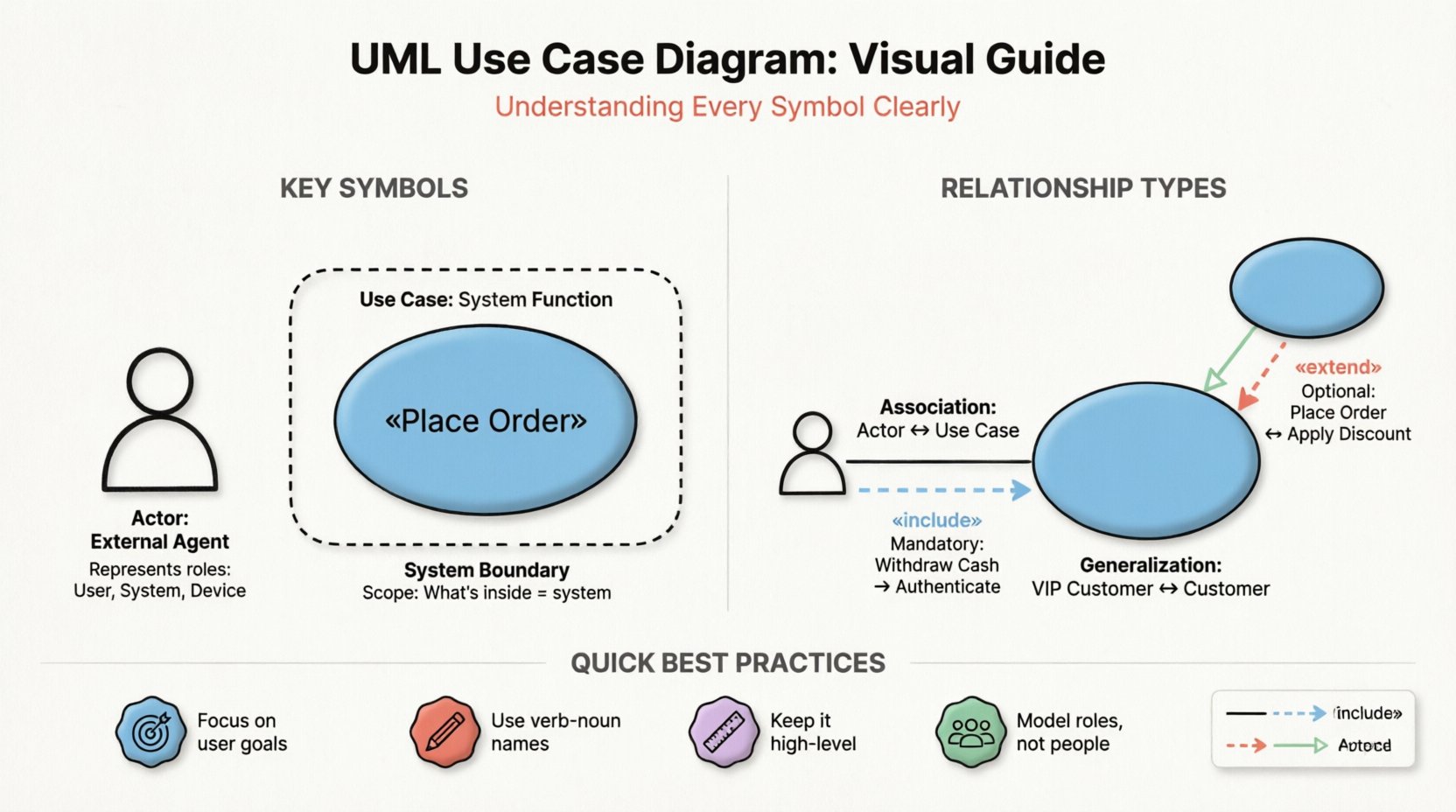
1. Association (Communication Link)
The association is the most basic relationship. It represents a connection between an actor and a use case, indicating that the actor initiates or participates in that function.
- Visual: A solid line connecting the actor to the oval.
- Direction: Can be bidirectional or unidirectional, though usually drawn as a simple line.
- Meaning: “The actor can perform this use case.”
2. Include Relationship
The include relationship is used when a use case always requires the behavior of another use case. It is a mandatory dependency.
- Visual: A dashed arrow pointing from the base use case to the included use case.
- Label: The arrow is labeled with «include».
- Meaning: “To do X, you must also do Y.”
- Example: “Withdraw Cash” includes “Authenticate User”. You cannot withdraw cash without authenticating first.
3. Extend Relationship
The extend relationship indicates optional behavior. A use case may be extended by another use case under specific conditions.
- Visual: A dashed arrow pointing from the extending use case to the base use case.
- Label: The arrow is labeled with «extend».
- Meaning: “If condition Z is met, then Y can happen during X.”
- Example: “Place Order” might be extended by “Apply Discount”. The discount is optional and depends on the customer’s status.
4. Generalization (Inheritance)
Generalization represents an inheritance relationship. One actor or use case is a specialized version of another.
- Visual: A solid line with a hollow triangle arrowhead.
- Direction: Points from the specific to the general.
- Actor Example: “VIP Customer” is a generalization of “Customer”. The VIP customer inherits all abilities of a standard customer.
- Use Case Example: “Pay with Credit Card” is a generalization of “Pay”. It is a specific way of performing the payment.
📊 Relationship Summary Table
| Relationship Type | Visual Style | Arrow Direction | Dependency | Example |
|---|---|---|---|---|
| Association | Solid Line | None (Line) | Interaction | User clicks button |
| Include | Dashed Line | Base to Included | Mandatory | Login required for Checkout |
| Extend | Dashed Line | Extender to Base | Optional | Apply Coupon (optional) |
| Generalization | Solid Line | Specific to General | Inheritance | Admin is a User |
📎 Advanced Elements: Notes and Constraints
Occasionally, a diagram needs additional information that cannot be conveyed through shapes and lines alone. UML provides specific symbols for annotations and constraints.
📝 Notes
Notes are used to provide comments, explanations, or additional details about a specific element.
- Visual: A rectangle with a folded corner (dog-ear).
- Connection: Connected via a dashed line to the element it describes.
- Usage: “Requires backend approval” or “Data must be encrypted”.
🔒 Constraints
Constraints are conditions that must be met for a use case or relationship to function correctly. They are often expressed as mathematical or logical expressions.
- Visual: Curly braces
{ }enclosing the condition. - Placement: Placed near the relevant element.
- Example:
{ balance > 0 }on a “Withdraw Money” use case.
🛠️ Guidelines for Effective Diagramming
Creating a diagram is an art that requires discipline. A cluttered diagram is useless. Follow these principles to ensure clarity and utility.
🎯 Focus on User Goals
Do not model system processes. Model user objectives. Instead of drawing “Save Database Entry”, draw “Record Customer Data”. The former describes the mechanism; the latter describes the value delivered to the user.
📏 Keep It High-Level
Use Case Diagrams are meant for high-level requirements. Do not include every single button click or validation check. If a use case becomes too complex, break it down into sub-use cases or move the detail to a different diagram (like a Sequence Diagram).
✅ Use Actor Roles
Never model a specific person (e.g., “John Smith”). Always model the role (e.g., “Sales Representative”). Roles persist even if personnel changes. This ensures the model remains valid over time.
🚫 Avoid Overlapping Boundaries
Ensure the system boundary clearly separates the system from the environment. If an actor is inside the box, it implies the actor is part of the system’s internal logic, which is incorrect.
❌ Common Mistakes to Avoid
Even experienced modelers make mistakes. Being aware of common pitfalls can save time during development.
- Mixing Levels of Abstraction: Combining high-level business goals with low-level technical tasks in the same diagram confuses the reader.
- Missing Actors: Failing to include external systems or time-based triggers (e.g., “Scheduled Report”).
- Incorrect Relationship Direction: Confusing Include and Extend directions is a frequent error. Remember: Include goes from the main use case to the sub-function. Extend goes from the optional feature to the main use case.
- Too Many Use Cases: A diagram with more than 10-15 use cases becomes hard to read. Consider splitting the system into subsystems.
- Using Use Cases for Non-Functional Requirements: Use Case Diagrams describe functionality. Performance, security, and scalability should be documented elsewhere.
🔄 Integration with Other UML Diagrams
A Use Case Diagram does not exist in isolation. It is the starting point for deeper analysis.
📜 Use Case Specifications
Each oval in the diagram should correspond to a text document describing the flow of events. This document details the preconditions, the main success scenario, and alternative paths.
🧵 Sequence Diagrams
Once the use cases are defined, Sequence Diagrams are used to map out the message flow between objects within the system to fulfill that use case.
🗺️ Activity Diagrams
For complex workflows within a use case, Activity Diagrams provide a flowchart-like view of the steps involved, including decision points and parallel processes.
🚀 Moving Forward
Mastering the Use Case Diagram is a foundational skill for system architects. It bridges the gap between business needs and technical implementation. By understanding the symbols, relationships, and boundaries, you create a blueprint that guides the entire development team.
Remember that the goal is clarity. A diagram that is easy to understand is a diagram that is useful. Regularly review your diagrams with stakeholders to ensure they still reflect the current requirements. As the project evolves, so should the model.
Apply these principles to your next project. Start with the actors, define the goals, draw the boundary, and connect the dots. With practice, you will find that creating these models becomes an intuitive part of your design process.