
Software architecture relies heavily on visual communication. Among the various modeling tools available, the UML Use Case Diagram stands out as a fundamental instrument for capturing functional requirements. However, as projects grow in complexity, these diagrams often suffer from visual clutter. A messy diagram obscures the very logic it is meant to clarify, leading to misunderstandings between stakeholders and developers.
This guide provides a structured approach to diagnosing and resolving common issues in UML modeling. We will explore how to identify visual noise, understand the root causes of diagram degradation, and apply systematic fixes to restore clarity. By following these protocols, teams can ensure their diagrams remain effective communication tools rather than sources of confusion.
🚨 Identifying the Signs of a Messy Diagram
Before attempting repairs, it is necessary to recognize what constitutes a problematic diagram. Visual clarity is subjective, but certain patterns consistently indicate a need for intervention. If your diagram exhibits the following symptoms, it requires immediate attention.
- Excessive Line Crossings: When relationship lines crisscross without a clear pattern, the eye struggles to follow the flow of interaction.
- Actor Proliferation: Having too many stick figures or actor labels creates a crowded perimeter that distracts from the core system behavior.
- Overlapping Elements: Use case ovals or actor rectangles overlapping each other make it difficult to distinguish boundaries.
- Inconsistent Notation: Mixing different shapes or line styles (e.g., solid vs. dashed) without a defined standard confuses the reader.
- Unlabeled Relationships: Arrows pointing between elements without labels for inclusion or extension relationships leave critical logic undefined.
- Scope Creep Visuals: The diagram contains low-level UI details or database operations that do not belong at the use case level.
Recognizing these symptoms is the first step in the troubleshooting process. A diagram that looks like a tangled web of string is often a reflection of a process that has evolved without governance.
🔍 Analyzing Root Causes
Fixing a diagram is not just about moving shapes around. It requires understanding why the mess occurred in the first place. Addressing the underlying cause prevents the issue from recurring during future updates.
1. Lack of Initial Scope Definition
Often, diagrams become messy because the boundaries of the system were not defined at the start. When a project expands, new use cases are added to the existing canvas without removing obsolete ones. This accumulation leads to a bloated diagram that tries to show everything at once.
2. Inconsistent Modeling Standards
Without a team-wide agreement on how to model actors, relationships, and hierarchies, every contributor creates their own style. One person might group use cases, while another places them randomly. This lack of standardization results in a fragmented visual language.
3. Failure to Abstract Complexity
Designers sometimes attempt to include every single interaction in a single view. While comprehensive, this approach overwhelms the viewer. Complex logic should be abstracted into sub-systems or included use cases rather than drawing every micro-interaction on the main canvas.
4. Static Diagrams in Dynamic Projects
Software requirements change frequently. If a diagram is created once and never updated, it becomes a historical artifact rather than a current reference. Stale diagrams accumulate comments, outdated labels, and deprecated relationships that clutter the view.
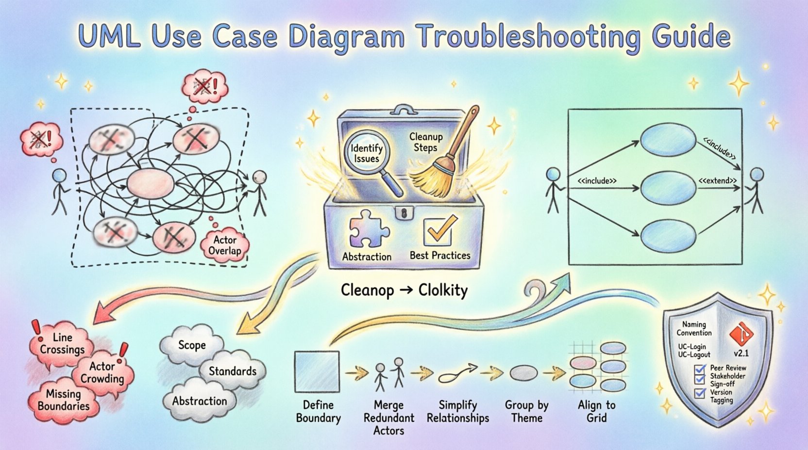
🧹 Step-by-Step Cleanup Process
Once the issues are identified and the causes understood, a systematic cleanup is required. Do not attempt to fix everything at once. Follow this workflow to methodically restore order.
Step 1: Define the System Boundary Clearly
Draw a box that represents the system under discussion. Ensure every use case inside this box belongs to the system, and every actor outside interacts with it. Anything outside this boundary is irrelevant to the current view. Remove any use cases that fall outside the intended scope.
Step 2: Consolidate Actors
Review the actors on the perimeter. Are there multiple actors that perform the same role? If so, merge them into a single generalized actor. For example, instead of having separate “Admin” and “SuperUser” actors if they share the same functions, consider a single “Administrator” actor. This reduces visual noise.
Step 3: Simplify Relationships
Examine the arrows connecting actors and use cases. Remove any redundant lines. Ensure that every relationship serves a purpose. If a use case is included in another, use the standard <
Step 4: Group Complex Use Cases
When a section of the diagram is too dense, consider creating a sub-diagram. If a specific process involves ten different steps, do not draw them all on the main canvas. Create a separate diagram for that subsystem and reference it.
Step 5: Align and Space Elements
Manually adjust the position of all shapes. Use a grid system if available in your environment. Ensure consistent spacing between ovals and rectangles. Align actor labels vertically and use case labels horizontally to create a clean rhythm.
📊 Common Issues and Solutions Table
The following table summarizes frequent problems encountered during modeling and the recommended corrective actions.
| Issue | Symptom | Solution |
|---|---|---|
| Overcrowded Center | Use cases overlap or are too close. | Expand the canvas, group related use cases, or create a sub-diagram. |
| Confusing Lines | Too many crossing association lines. | Reposition actors to reduce line crossings; use orthogonal routing. |
| Unclear Scope | System boundary is missing or vague. | Draw a distinct rectangle labeled with the system name. |
| Too Many Actors | Perimeter is full of small labels. | Generalize actors; remove internal system users from the diagram. |
| Ambiguous Relationships | Arrows without labels or mixed types. | Standardize labels (< |
🛡️ Best Practices for Long-Term Clarity
Once the diagram is clean, the goal is to keep it that way. Maintenance is often harder than creation. Implementing habits that promote simplicity will save time in the future.
Adopt a Naming Convention
Establish a rule for how use cases and actors are named. A common pattern is “Verb + Object” for use cases (e.g., “Generate Report”, “Log In User”). Avoid abstract nouns like “Process” or “Manage” without context. Consistent naming helps stakeholders scan the diagram quickly.
Limit the Level of Detail
Use Case Diagrams are meant for high-level requirements, not detailed flowcharts. If you find yourself adding decision diamonds or loop structures, you are likely describing a flowchart, not a use case. Keep the focus on the interaction, not the internal logic.
Version Control Your Models
Treat your diagram files as code. Save versions when significant changes occur. This allows you to revert if a cleanup attempt makes things worse. It also helps track how the system requirements evolved over time.
Review Before Release
Include diagram review in your development workflow. Before a sprint ends or a milestone is reached, have a peer review the diagrams. Ask specific questions: “Can a new developer understand the actors?” and “Is the boundary clear?”.
🤝 Managing Complexity Through Abstraction
As systems grow, the need for abstraction increases. Trying to fit a large enterprise system into a single use case diagram is rarely feasible. You must learn to delegate complexity to other diagrams.
- Package Diagrams: Use packages to group related use cases. This creates a folder-like structure that can be expanded or collapsed.
- Reference Diagrams: Point to a separate diagram for complex subsystems. Label the reference clearly (e.g., “See Diagram B for Payment Details”).
- Sequence Diagrams: Move detailed interaction flows to sequence diagrams. Use case diagrams show what happens; sequence diagrams show how it happens.
By offloading detail, your primary diagram remains a high-level map of the system’s functionality. This separation of concerns is critical for maintaining a clean visual hierarchy.
🔄 Collaboration and Review Cycles
A diagram is a communication tool. If only one person understands it, it has failed. Regular review cycles ensure the diagram reflects the consensus of the team.
During reviews, focus on the following:
- Completeness: Are all critical requirements covered?
- Consistency: Do all team members follow the same style guide?
- Accuracy: Do the actors match the actual user roles in the application?
- Clarity: Can a stakeholder without technical training understand the diagram?
When conflicts arise during reviews, prioritize simplicity. If two people interpret a line differently, redraw it. If a use case is disputed, split it into smaller, more specific cases. It is better to have more diagrams with fewer elements than one diagram with too many elements.
🧩 Handling Edge Cases and Exceptions
Every system has exceptions. Error handling, alternative flows, and security constraints often clutter diagrams. Do not draw every exception as a primary use case.
Instead, use the <
📈 Monitoring Diagram Health
Just as code requires refactoring, diagrams require maintenance. Set a schedule to audit your diagrams. Look for:
- Use cases that have not been updated in six months.
- Actors that no longer interact with the system.
- Lines that connect to nothing or loop back on themselves unnecessarily.
Removing dead weight is just as important as adding new features. A lean diagram is easier to read, easier to update, and easier to maintain.
🎯 Finalizing the Cleanup
When you have completed the restructuring, verify the diagram against the project requirements document. Ensure that every requirement has a corresponding use case. Check that every actor has a defined purpose. If the diagram looks balanced, with clear boundaries and minimal crossing lines, the troubleshooting process is complete.
Remember that a diagram is never truly finished. It is a living document that evolves with the software. The goal is not perfection, but clarity. If a new developer can look at the diagram and understand the system’s core functionality in under five minutes, you have succeeded.
🚀 Moving Forward
Applying these troubleshooting techniques transforms your modeling workflow. You move from reactive patching to proactive design. By maintaining clean, standardized, and well-structured diagrams, you reduce the cognitive load on your team and stakeholders. This clarity translates into fewer errors during development and a more robust final product.
Start auditing your current diagrams today. Identify the messiest section, apply the cleanup steps, and observe the improvement in communication. Consistency in modeling is a hallmark of professional engineering practice.