
Effective software development relies heavily on clear communication between business stakeholders and technical teams. One of the most powerful tools for bridging this gap is the Unified Modeling Language (UML) Use Case Diagram. These diagrams provide a visual representation of how users interact with a system, translating abstract requirements into concrete technical specifications. However, simply drawing lines and boxes is not enough. The true value lies in the collaborative process used to create and validate them.
This guide outlines the essential practices for working with developers to create accurate, useful, and maintainable Use Case Diagrams. By following structured approaches, teams can reduce ambiguity, prevent scope creep, and ensure that the final product aligns with user needs.
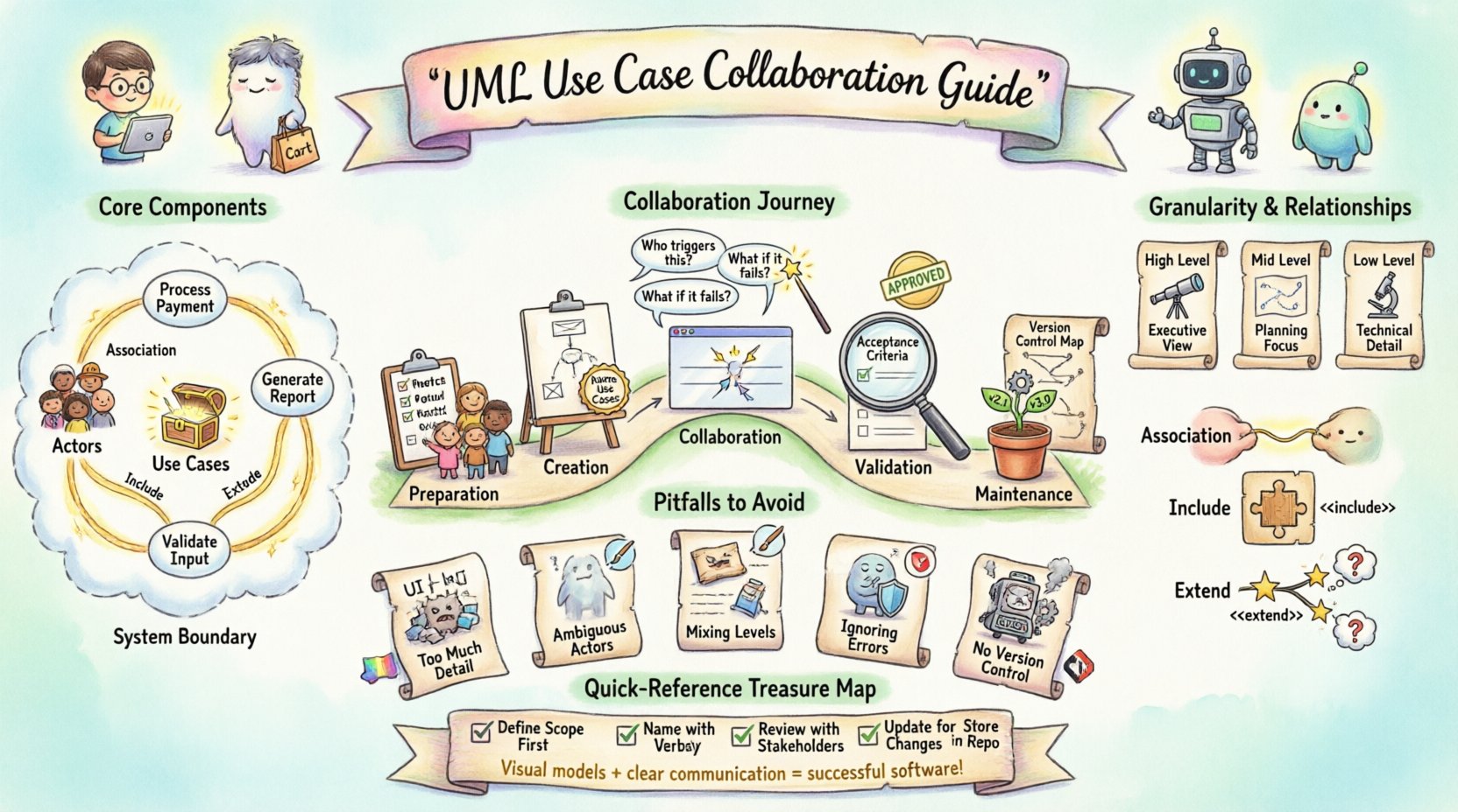
🧠 Understanding the Core Components
Before diving into collaboration strategies, it is crucial to understand the fundamental elements that make up a Use Case Diagram. Both business analysts and developers must share a common vocabulary to avoid misinterpretation.
- Actors: Entities that interact with the system. These can be human users, external systems, or hardware devices.
- Use Cases: Specific functionalities or goals that the system provides to an actor. They represent a complete unit of functionality.
- System Boundary: A box that defines the scope of the system, separating internal processes from external actors.
- Relationships: The connections between actors and use cases, indicating how they interact.
When collaborating, ensure that every developer understands the distinction between an Actor and a User Interface. An Actor is not a specific screen; it is the role the person or system plays. Clarifying this early prevents confusion during the coding phase.
📋 Preparation Before Modeling
Starting a diagram without preparation often leads to rework. A disciplined approach to the preparation phase sets the stage for a smoother collaboration session.
1. Identify Stakeholders Early
Invite the right people to the modeling session. This includes product owners, end-users, and lead developers. Their presence ensures that requirements are captured from multiple perspectives.
2. Define the System Scope
Clearly articulate what the system will and will not do. A common pitfall is allowing the diagram to grow indefinitely. Use the system boundary to explicitly mark the limits of the current project.
3. Gather Requirements Documentation
Have any existing user stories, functional specifications, or business rules ready. These documents serve as the source material for the diagram. They provide the evidence needed to justify why a specific use case exists.
4. Set Collaboration Goals
Define what you want to achieve in the session. Are you trying to identify missing features? Are you validating a specific workflow? Having a clear objective keeps the discussion focused.
🎨 Creating the Diagram: Standards & Notation
Consistency is key when creating diagrams that multiple people will read. Developers need to trust that the diagram accurately reflects the logic they will implement.
Use Case Naming Conventions
Use case names should follow a verb-noun structure. This makes them readable and action-oriented.
- Correct: Process Payment, Generate Report, Update Profile.
- Incorrect: Payment, Report, User Data.
Using action verbs helps developers understand the expected behavior. It also makes it easier to map these names to method names in the code.
Granularity Levels
Decide on the level of detail required. A high-level diagram is good for executive summaries, while a detailed diagram is necessary for implementation. Avoid mixing levels of granularity in the same diagram.
| Level | Focus | Best Used For |
|---|---|---|
| High-Level | Major system goals | Stakeholder alignment, Scope definition |
| Mid-Level | Key workflows | Project planning, Sprint estimation |
| Low-Level | Specific interactions | Technical design, Unit testing |
Relationship Types
Understanding the three main relationships is vital for technical accuracy.
- Association: A link between an actor and a use case. It implies the actor initiates or participates in the use case.
- Include: Indicates that one use case incorporates the behavior of another. This is used for reusable functionality (e.g., Login is included in Place Order).
- Extend: Indicates optional behavior that adds to the base use case under specific conditions (e.g., Apply Discount extends Place Order).
🗣️ Facilitating the Collaboration Session
The actual meeting where the diagram is created or reviewed is the most critical part of the process. This is where misunderstandings are resolved.
Walkthroughs and Live Editing
Conduct live walkthroughs of the diagram. Point to each actor and use case and ask the group to describe what happens. If the diagram is digital, allow developers to edit it in real-time to capture immediate feedback. This creates a shared artifact rather than a static document.
Questioning Techniques
Use open-ended questions to dig deeper. Avoid leading questions that suggest the answer.
- “What happens if the user cancels during this step?”
- “Does this use case require data from the external system?”
- “Who is the primary actor for this functionality?”
Documentation of Decisions
Record the decisions made during the session. If a specific use case was removed or a relationship changed, note the reason. This creates an audit trail that helps when requirements change later.
Traceability
Ensure every use case can be traced back to a business requirement. Developers need to know the why behind the what. This helps them prioritize tasks and make better architectural decisions.
✅ Validation and Sign-off
Once the diagram is drafted, it must be validated before development begins. This step ensures that the visual model matches the intended logic.
Review against Acceptance Criteria
Compare the diagram against the acceptance criteria for each feature. Does the diagram cover all the scenarios described in the criteria? If not, update the diagram.
Technical Feasibility Check
Have the lead developer review the diagram from an implementation standpoint. Are there use cases that are technically impossible or require disproportionate effort? Identifying these issues early saves significant resources.
Formal Approval
Obtain formal sign-off from key stakeholders. This does not mean every detail is perfect, but it means the scope is agreed upon. This agreement protects the team from scope creep later in the project.
🚫 Common Pitfalls to Avoid
Even experienced teams can fall into traps that reduce the effectiveness of Use Case Diagrams. Being aware of these pitfalls helps maintain quality.
- Too Much Detail: Do not include UI elements or internal database logic. Keep the focus on user goals.
- Ambiguous Actors: Avoid generic actors like System or User without specific roles. Use Customer or Administrator instead.
- Mixing Levels: Do not show a high-level goal alongside a detailed step. Keep the diagram consistent in its depth.
- Ignoring Error Flows: Use cases should cover error scenarios, not just happy paths. Ensure Cancel, Retry, and Timeout behaviors are considered.
- Lack of Version Control: Treat the diagram as code. Store it in a version control system to track changes over time.
🔄 Maintenance Over Time
Software is rarely static. As the product evolves, the Use Case Diagram must evolve with it. Neglecting maintenance leads to outdated documentation that misleads developers.
Change Management
Establish a process for updating the diagram. When a requirement changes, the diagram should be updated immediately. Do not wait until the next major release.
Regular Reviews
Schedule periodic reviews of the diagrams. This ensures they remain accurate as the system matures. A quarterly review is often sufficient for mature projects.
Integration with Documentation
Link the Use Case Diagram to other documentation. If a user guide or API documentation references a feature, ensure the diagram reflects the current state of that feature.
📊 Collaboration Checklist
Use this checklist to ensure all bases are covered during the collaboration process.
| Step | Question | Status |
|---|---|---|
| Scope Definition | Is the system boundary clearly marked? | ☐ |
| Actor Identification | Are all actors distinct and necessary? | ☐ |
| Use Case Naming | Are names verb-noun phrases? | ☐ |
| Relationships | Are Include/Extend relationships used correctly? | ☐ |
| Validation | Have developers confirmed technical feasibility? | ☐ |
| Approval | Is there stakeholder sign-off? | ☐ |
🔗 Deep Dive: Actor Identification Strategies
Identifying the correct actors is often the most challenging part of the process. An actor represents a role, not a specific person. Here are strategies to ensure accuracy.
- Role-Based Analysis: Look at the different roles people play in the business process. For example, a person might be a Customer when buying and an Employee when reporting.
- External System Analysis: Identify any third-party services that interact with your system. These should be modeled as actors.
- Hardware Interaction: If hardware devices interact with the software (e.g., a scanner or a sensor), they are actors.
- Time-Based Actors: Sometimes a system interacts with itself at a scheduled time. This is often modeled as a Timer actor.
When in doubt, ask: “Who or what initiates this action?” If the answer is a specific entity, it is likely an actor.
🔗 Deep Dive: Handling Complex Relationships
Complex systems often require complex relationships. Misusing relationships can lead to logical errors in the design.
Include vs. Extend
Confusion often arises between Include and Extend. The distinction lies in control and necessity.
- Include: The included use case is mandatory. The base use case cannot complete without it. Example: Withdraw Cash includes Verify PIN.
- Extend: The extending use case is optional. It only happens under specific conditions. Example: Print Receipt extends Withdraw Cash only if the user requests it.
Generalization
Use generalization to represent inheritance. If one actor is a specialized version of another, use a generalization arrow. For example, a VIP Customer is a type of Customer.
🔗 Deep Dive: Communication During Development
The diagram is not a one-time deliverable. It serves as a reference point throughout the development lifecycle.
- Onboarding: Use the diagram to onboard new developers. It provides a quick overview of system functionality.
- Code Reviews: Refer to the diagram during code reviews. Does the implementation match the modeled behavior?
- Testing: Use the use cases to create test cases. Each use case should correspond to a set of test scenarios.
- Support: When users report issues, the diagram helps support teams understand the intended flow.
Maintaining this connection between the model and the code ensures integrity. It prevents the drift that often occurs when documentation is ignored.
🔗 Deep Dive: Managing Scope Creep
One of the biggest threats to project success is scope creep. Use Case Diagrams are an effective tool to manage this.
- Visual Boundaries: When a new feature is requested, check if it fits within the current system boundary. If it requires a new boundary, it is a new system.
- Impact Analysis: Use the diagram to show the impact of changes. If adding a use case affects multiple actors, the cost is higher.
- Prioritization: Use the diagram to prioritize features. Core use cases should be built first. Optional extensions can be deferred.
By keeping the diagram visible, stakeholders can see the trade-offs involved in adding new functionality. This transparency fosters better decision-making.
🔗 Deep Dive: Technical Implementation Considerations
Developers need specific information from the diagram to write efficient code.
- Input Data: The diagram should imply what data is needed to start the use case.
- Output Data: The diagram should imply what data is produced at the end.
- Exceptions: While not always drawn explicitly, developers should know the error conditions associated with each use case.
- Performance: Complex relationships might indicate performance bottlenecks. Discuss these with the architecture team.
Collaboration ensures that these technical considerations are addressed during the modeling phase, rather than after implementation has begun.
🔗 Deep Dive: Versioning the Diagram
Just like source code, diagrams need versioning. This allows teams to revert to previous states if necessary.
- Version Numbers: Use semantic versioning (e.g., v1.0, v1.1) for the diagrams.
- Change Logs: Maintain a log of what changed between versions. This helps in understanding the evolution of the system.
- Baselines: Create baselines for major milestones. This locks the scope for a specific release.
This discipline ensures that there is always a record of what the system was supposed to be at any given point in time.