
Creating a robust software architecture begins long before the first line of code is written. It starts with clarity. Specifically, it starts with defining the scope of the system you are building. In the world of Unified Modeling Language (UML), the Use Case Diagram serves as a primary tool for visualizing functional requirements and interactions. However, a diagram without a clear system boundary is like a map without a border. It leaves developers, stakeholders, and testers guessing about what belongs to the project and what remains external.
This guide explores the critical concept of system boundaries within UML Use Case Diagrams. We will examine how to delineate what is inside your system, how to classify actors correctly, and why precision here prevents costly errors later in the development lifecycle. We will move beyond simple visual representation to discuss the architectural implications of your boundary choices.
Understanding the System Boundary Concept 🧱
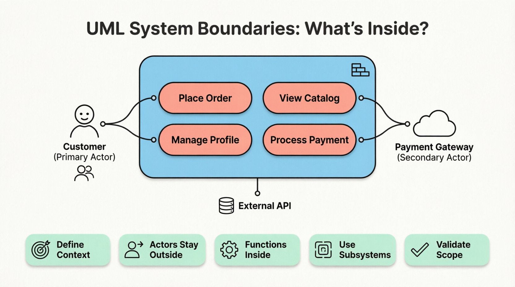
In UML modeling, the system boundary is typically represented by a rectangle that encloses the use cases. This rectangle defines the perimeter of the system under consideration. Everything inside this box is part of the system’s responsibility. Everything outside is external to it.
- Inside the Box: Functions, processes, and logic that the system performs.
- Outside the Box: Users, external systems, hardware, and environmental factors that trigger or receive data from the system.
- The Line: The boundary itself represents the interface between the system and the outside world.
Defining this boundary is not merely a drawing exercise; it is a contractual agreement on scope. If a use case falls inside the boundary, the system must implement the logic to fulfill it. If it falls outside, the system must only react to it or facilitate it through an interface.
Why Ambiguity is the Enemy of Scope
When the boundary is vague, scope creep becomes inevitable. Developers might assume they need to build a feature that the client expects to be a third-party service. Alternatively, the team might neglect a core function because they assumed it was external. A precise boundary eliminates this ambiguity.
Consider the difference between a system that manages its own user authentication versus one that relies on an external Identity Provider. If the boundary includes the authentication logic, the system must handle passwords, security tokens, and account recovery flows. If the boundary sits at the login screen, the system simply delegates that responsibility. The visual boundary dictates the workload.
The Role of Actors in Relation to Boundaries 👥
Actors represent the roles that interact with the system. They are distinct from the system itself. Understanding where an actor sits relative to the boundary is crucial for accurate modeling.
Actors are always placed outside the system boundary. They initiate interactions or receive outputs. However, not all actors are human users. Some are external systems, hardware devices, or even other software processes.
Primary vs. Secondary Actors
- Primary Actors: These actors initiate the use case. They start the process. For example, a Customer clicking “Submit Order”.
- Secondary Actors: These actors provide a service to the system in response to a request. For example, a Payment Gateway processing the transaction initiated by the Customer.
Both types of actors remain outside the boundary. The line separates the system’s internal logic from the external trigger or support mechanism.
| Element | Position | Responsibility |
|---|---|---|
| Use Case | Inside Boundary | Encapsulate a specific function or goal. |
| Actor | Outside Boundary | Initiate interaction or consume output. |
| Association Line | Crosses Boundary | Indicates communication path. |
Internal Processes vs. External Interactions 🔄
One of the most common challenges in modeling is determining whether a specific process belongs inside or outside the boundary. This decision often depends on the perspective of the system being modeled.
Defining the System Context
Before drawing the rectangle, you must define what the system is. Is it the entire enterprise software suite, or just the mobile application component? The answer changes the boundary.
- Narrow Scope: If you are modeling a specific module, external databases and legacy systems are actors outside the boundary.
- Broad Scope: If you are modeling the entire enterprise platform, the database might be internal, but the external payment processor remains outside.
When you expand the boundary, use cases that were previously external interactions become internal processes. This shift changes the implementation requirements significantly. For instance, if a data validation rule is external, the client application handles it. If it is internal, the server must enforce it.
Interfaces as the Boundary Edge
The boundary is effectively an interface. It is where data enters and leaves. Every association line crossing the boundary represents a communication channel. This could be an API call, a user input, a network packet, or a physical action.
It is vital to ensure that every use case inside the boundary has at least one association line crossing the boundary. A use case with no interaction with an actor is a hidden function that has no defined entry point. This usually indicates a modeling error or a missing requirement.
Subsystems and Nested Boundaries 🗂️
Large systems are rarely monolithic. They are often composed of subsystems. When modeling complex architectures, you might need to represent boundaries within boundaries. This is known as a subsystem or nested boundary.
Why Use Subsystems?
Subsystems help manage complexity. They allow you to hide internal details of a component while exposing a clean interface to the rest of the system.
- Abstraction: You can model the Order Processing subsystem without detailing every database query it performs.
- Encapsulation: Changes within the subsystem do not affect the external actors, provided the interface remains stable.
- Team Allocation: Different boundaries can represent ownership by different development teams.
In a UML diagram, a subsystem is drawn as a smaller rectangle inside the main system boundary. Use cases within this subsystem are still part of the main system but belong to a specific component.
Extending the Model
When using subsystems, ensure that actors interact with the subsystem boundary appropriately. Sometimes, an actor interacts directly with the main system, which then delegates to a subsystem. Other times, an actor might interact directly with a subsystem if that component exposes its own interface.
Common Pitfalls and How to Avoid Them 🚫
Even experienced modelers make mistakes when defining boundaries. Recognizing these pitfalls helps you refine your diagrams and ensure they accurately reflect the architecture.
| Pitfall | Description | Correction |
|---|---|---|
| Scope Creep | Adding features that belong to external systems inside the boundary. | Review requirements to identify third-party dependencies. |
| Missing Actors | Failing to include all entities that trigger use cases. | Conduct stakeholder interviews to identify all users. |
| Overlapping Boundaries | Multiple diagrams with conflicting definitions of the system. | Standardize the system context across all documentation. |
| Logic Leakage | Placing business logic in the user interface layer. | Ensure business rules reside within system use cases. |
Pitfall 1: Including Technical Implementation Details
Use Case Diagrams focus on what the system does, not how it does it. Avoid drawing technical components like databases, servers, or file systems inside the boundary as if they were actors. These are internal implementation details, not functional interactions.
Pitfall 2: Confusing Objects with Actors
An object in a class diagram is not an actor. An actor represents a role. A Customer is an actor. A Customer Object is a data structure inside the system. Do not place data objects outside the boundary unless they represent an external data source.
Validation and Maintenance of Boundaries 🛡️
Once the boundary is drawn, it must be validated. A diagram that looks correct but does not match reality is worse than no diagram at all. Regular reviews ensure the model stays aligned with the evolving system.
Stakeholder Walkthroughs
Present the diagram to stakeholders. Ask them to identify what is inside and what is outside. If they disagree with the placement of a use case, it indicates a misunderstanding of the project scope. This discussion is often more valuable than the diagram itself.
Traceability to Requirements
Link every use case inside the boundary to a specific requirement document. If a requirement exists but has no use case inside the boundary, the system does not support it. If a use case exists but has no requirement, it is likely scope creep.
Version Control
As the system evolves, the boundary might shift. A feature that was once a third-party integration might become an internal module. Update the diagram to reflect these changes. Do not let the diagram become a relic of a past version.
Ensuring Long-Term Clarity 🔍
A well-defined system boundary serves as a reference point throughout the entire software lifecycle. It informs testing strategies, deployment plans, and maintenance efforts.
- Testing: Testers know which use cases to verify and which to expect from external integrations.
- Deployment: Deployment teams understand which components need to be installed versus which are cloud-based services.
- Maintenance: When a bug occurs, the boundary helps determine if the issue is within the codebase or caused by an external input.
By treating the system boundary as a critical architectural decision rather than a drawing convention, you build a foundation for a stable and understandable system. This precision reduces friction between teams and ensures that the final product meets the intended functional goals.
Summary of Key Principles 📝
To summarize the approach to defining system boundaries in UML Use Case Diagrams:
- Define Context Clearly: Determine what the system is before drawing the box.
- Keep Actors External: Users and external systems always reside outside the boundary.
- Focus on Function: Place only functional use cases inside the boundary.
- Use Subsystems for Complexity: Nest boundaries to manage large-scale architecture.
- Validate with Stakeholders: Ensure the model matches the agreed-upon scope.
Attention to these details ensures that your diagrams communicate effectively. They become tools for collaboration rather than just documentation artifacts. A clear boundary protects the team from ambiguity and sets the stage for successful delivery.