
Software development projects often fail not because of bad code, but because of bad requirements. The bridge between a vague idea and a functional system is built using modeling techniques. Among these, the UML Use Case Diagram is a cornerstone for defining system behavior. However, when constructed incorrectly, this diagram becomes a liability rather than an asset. It is the primary vehicle through which scope creep enters the development lifecycle. Scope creep occurs when project requirements expand beyond the original agreement without adjustments to time, budget, or resources. When a Use Case Diagram fails to clearly define boundaries, actors, or interactions, it invites ambiguity that developers interpret as permission to add features. This guide examines the specific modeling errors that trigger this phenomenon and provides technical corrections to maintain control over project delivery.
📐 The Relationship Between Modeling and Scope
A Use Case Diagram is a static representation of the system’s dynamic behavior. It visualizes the interactions between external entities (actors) and the system itself. It serves as a contract. When stakeholders review this diagram, they implicitly agree to the functionality depicted. If the diagram is vague, the agreement is flawed. Ambiguity in the diagram leads to ambiguity in the requirements document, which leads to ambiguity in the code.
Scope creep is often described as “feature creep.” It happens when a developer decides a feature “would be nice” or when a stakeholder remembers a requirement during the testing phase. A well-constructed Use Case Diagram acts as a firewall against these additions. It defines the perimeter. If a requirement falls outside the drawn boundaries, it is flagged as out-of-scope. If the boundaries are drawn loosely, everything is considered in-scope.
🔍 Mistake 1: Misidentifying Actors
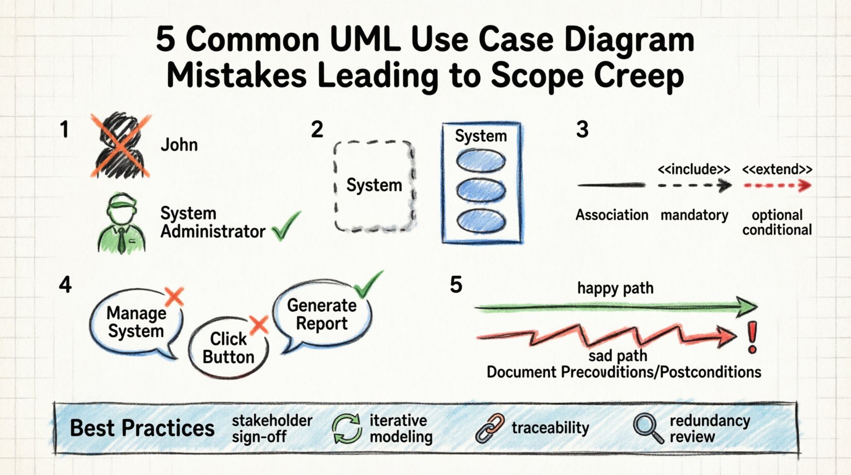
One of the most common errors involves the definition of actors. An actor represents a role played by a user or an external system that interacts with the solution. It does not represent a specific person, but a function or a type of user.
The Error
Modelers often mistake specific individuals for actors. For example, labeling an actor “John the Manager” instead of “System Administrator.” This limits the diagram to a single instance rather than a role. Worse, modelers often include internal roles that should be treated as system components. If a database is an actor, it implies the system relies on an external entity for core processing, which complicates the boundary.
The Consequence
When actors are misidentified, requirements gathering becomes inefficient. The team might spend time defining permissions for “John” rather than the role of “Manager.” This leads to over-engineering specific user interfaces for specific people instead of designing for the role. Additionally, if an internal component is modeled as an external actor, it suggests that the system must manage a separate communication protocol for it. This adds unnecessary complexity and potential points of failure.
The Correction
- Use Generic Roles: Always name actors by their function (e.g., “Customer,” “Auditor,” “Payment Gateway”).
- Exclude Internal Components: Database servers, operating systems, and other internal modules should not be actors unless they are external to the system boundary.
- Define Relationships: Ensure every actor has a clear reason for being in the diagram. If an actor has no connections to use cases, remove it.
🔒 Mistake 2: Blurring System Boundaries
The system boundary is the box that encloses the use cases. It defines what is inside the software and what is outside. This is the most critical line to draw accurately.
The Error
Developers frequently draw the boundary too loosely. They include business processes that the software only supports but does not execute. For instance, if a use case is “Approve Loan,” is the software doing the approval, or is it just recording the approval? If the software is just recording, the approval logic belongs in a separate business process model, not inside the system boundary.
Another common error is including data storage inside the boundary as if it were a process. Data should be passive. Only processes (use cases) should be inside the box.
The Consequence
When the boundary is too wide, the project scope expands to include business logic that is not part of the software development. The team ends up building rules engines or workflow systems that should have been manual or handled by a different tool. This increases the timeline and budget significantly. Conversely, if the boundary is too narrow, critical functionality is left out, leading to patchwork fixes later.
The Correction
- Focus on Interaction: Only include use cases where the system performs an action in response to an actor.
- Clear Separation: Ensure that business rules are documented separately from system processes.
- Visual Clarity: Keep the box distinct. If a process is external, it should be outside the box.
🔗 Mistake 3: Confusing Relationships
UML provides specific arrows to denote relationships between use cases: Association, Include, and Extend. Misusing these is a technical debt trap.
The Error
Modelers often use the Include relationship for optional functionality. The Include relationship implies that the included use case is a mandatory part of the base use case. It is a dependency. If the base use case cannot happen without the included one, use Include. However, many teams use Include for “nice-to-have” features.
Similarly, the Extend relationship is used incorrectly. Extend implies optional behavior that only occurs under specific conditions. If a team uses Extend for mandatory validation steps, they create confusion about whether the step is required.
The Consequence
This confusion directly impacts testing and development. If a feature is marked as Include, developers build it as mandatory. If it is marked as Extend, they might build it as optional. If the requirement changes, the diagram does not reflect the change accurately. This leads to scope creep because the team must revisit the diagram to correct the logic, and during that correction, new features often get added to “fix” the logic flow.
The Correction
| Relationship | Meaning | When to Use |
|---|---|---|
| Association | Actor interacts with Use Case | When an actor initiates the process. |
| Include | Mandatory sub-process | When a step is always required (e.g., Login). |
| Extend | Optional conditional behavior | When a step only happens if a condition is met (e.g., Apply Discount). |
📉 Mistake 4: Improper Granularity
Granularity refers to the level of detail in the use cases. A diagram can suffer from being too high-level or too low-level.
The Error
Too High-Level: A use case labeled “Manage System” is useless. It does not tell the developer what functions are included. This forces the development team to guess the scope, leading to assumptions that become requirements.
Too Low-Level: A use case labeled “Click Button” is also wrong. This describes an interaction, not a function. It forces the design to focus on UI elements rather than business value. It leads to micro-management of the interface.
The Consequence
High-level diagrams lead to scope creep because the team fills in the blanks with features they think are necessary. Low-level diagrams lead to scope creep because stakeholders see the UI and say, “Oh, I also want this button to do this.” By focusing on the wrong level, the diagram invites stakeholder interference in design details that should be decided later.
The Correction
- Use Action Verbs: Use case names should be Verb + Object (e.g., “Generate Report,” “Update Password”).
- Value-Based: Each use case should deliver a discrete unit of value to the actor.
- Standardize: Keep all use cases at a similar level of abstraction.
⚠️ Mistake 5: Ignoring Exception Flows
Use Case Diagrams typically show the “Happy Path.” They show what happens when everything goes right. They often omit the “Sad Path” or exception flows.
The Error
Modelers draw the successful flow and assume the system handles errors automatically. They do not explicitly model error handling use cases or conditions. This creates a gap between the diagram and the code.
The Consequence
When development begins, the team must decide how to handle errors. Since it was not modeled, this decision is made during implementation. This is a classic point for scope creep. A developer might implement a complex error recovery system that was not budgeted. Or, they might implement a simple error message that fails to meet compliance standards. The lack of modeling means the scope for error handling is undefined.
The Correction
- Document Preconditions: Clearly state what must be true before a use case starts.
- Document Postconditions: Define the state of the system after the use case finishes.
- Include Error Scenarios: If an error path changes the system state significantly, model it as a separate use case or explicitly note it in the description.
📈 The Ripple Effect on Development
When these mistakes occur, the impact spreads through the entire software development life cycle. It is not just a diagram problem; it is a project management problem.
- Design Phase: Architects design databases based on incorrect actor definitions, leading to schema changes later.
- Development Phase: Developers implement features that are technically unnecessary because the boundary was unclear.
- Testing Phase: Testers cannot create accurate test cases because the expected behavior was not fully modeled.
- Deployment Phase: Users request features that should have been modeled but were not, leading to post-launch patches.
Each phase adds cost. The cost of fixing a requirement error during modeling is low. The cost of fixing it during deployment is exponentially higher. This cost inflation is the financial definition of scope creep.
🛡️ Best Practices for Prevention
To prevent scope creep, the modeling phase must be rigorous. It requires discipline and a commitment to accuracy.
- Stakeholder Validation: Do not finalize the diagram without sign-off from key stakeholders. If they agree to the box and the arrows, they agree to the scope.
- Iterative Modeling: Do not try to draw the perfect diagram in one go. Start with high-level actors, then refine. This allows for early detection of boundary issues.
- Traceability: Link every use case to a requirement ID. If a requirement cannot be traced to a use case, it is likely scope creep.
- Review for Redundancy: Regularly audit the diagram for duplicate use cases. Duplicate functionality is a clear indicator of poor planning.
📊 Comparison of Modeling Approaches
Understanding the difference between a flawed approach and a robust approach is essential for avoiding common pitfalls.
| Feature | Flawed Approach | Robust Approach |
|---|---|---|
| Actor Naming | Specific Person (e.g., “Bob”) | Role (e.g., “Manager”) |
| System Boundary | Includes business processes | Includes only system actions |
| Relationships | Generic lines | Specific (Include/Extend) |
| Detail Level | UI specific (Click Button) | Function specific (Save Data) |
| Documentation | Diagram only | Diagram + Use Case Descriptions |
🔎 Final Thoughts on Scope Control
The UML Use Case Diagram is more than a drawing; it is a communication tool. It translates business needs into technical specifications. When this translation is accurate, the project stays on track. When it is inaccurate, the project drifts.
Scope creep is not always malicious. Often, it is the result of good intentions and unclear boundaries. By identifying the common mistakes in actor definition, system boundaries, and relationships, teams can build a stronger foundation. This foundation supports stable development and predictable delivery. It ensures that the final product matches the initial agreement, saving time and resources.
Investing time in a precise model pays dividends during implementation. It reduces the need for rework. It clarifies expectations. It protects the team from unnecessary feature requests. A disciplined approach to modeling is the most effective defense against scope creep.