
Building systems that grow without breaking is a fundamental challenge in software architecture. As applications expand in complexity, the behavior of individual components becomes harder to predict. This is where modeling techniques prove essential. Specifically, the Unified Modeling Language (UML) State Machine Diagram, often called a State Diagram, offers a rigorous way to visualize the lifecycle of an object or system. By mapping out states, transitions, and events, architects can anticipate bottlenecks and ensure that the system remains stable under load. 🧠
This guide explores how to leverage state diagrams not just for documentation, but as an active tool for designing scalable infrastructure. We will move beyond basic definitions to examine how these diagrams influence concurrency, resource management, and error handling. The goal is to create a robust foundation that supports growth without requiring a complete rewrite. 🚀
Understanding the State Machine Diagram ⚙️
A state diagram describes the dynamic behavior of a single object in response to events. It defines the sequence of states an object passes through during its lifetime. Unlike a class diagram, which shows static structure, a state diagram focuses on behavior over time. For scalable systems, this distinction is critical. You cannot scale what you do not understand, and you cannot understand complex behavior without visualizing the flow.
Why State Diagrams Matter for Scalability 📈
Scalability is often treated as a performance problem, solved by adding more servers or optimizing databases. However, scalability is also an architectural problem. If the logic governing an object is convoluted, adding resources does not help; it often compounds the issue. State diagrams help identify these logical complexities early.
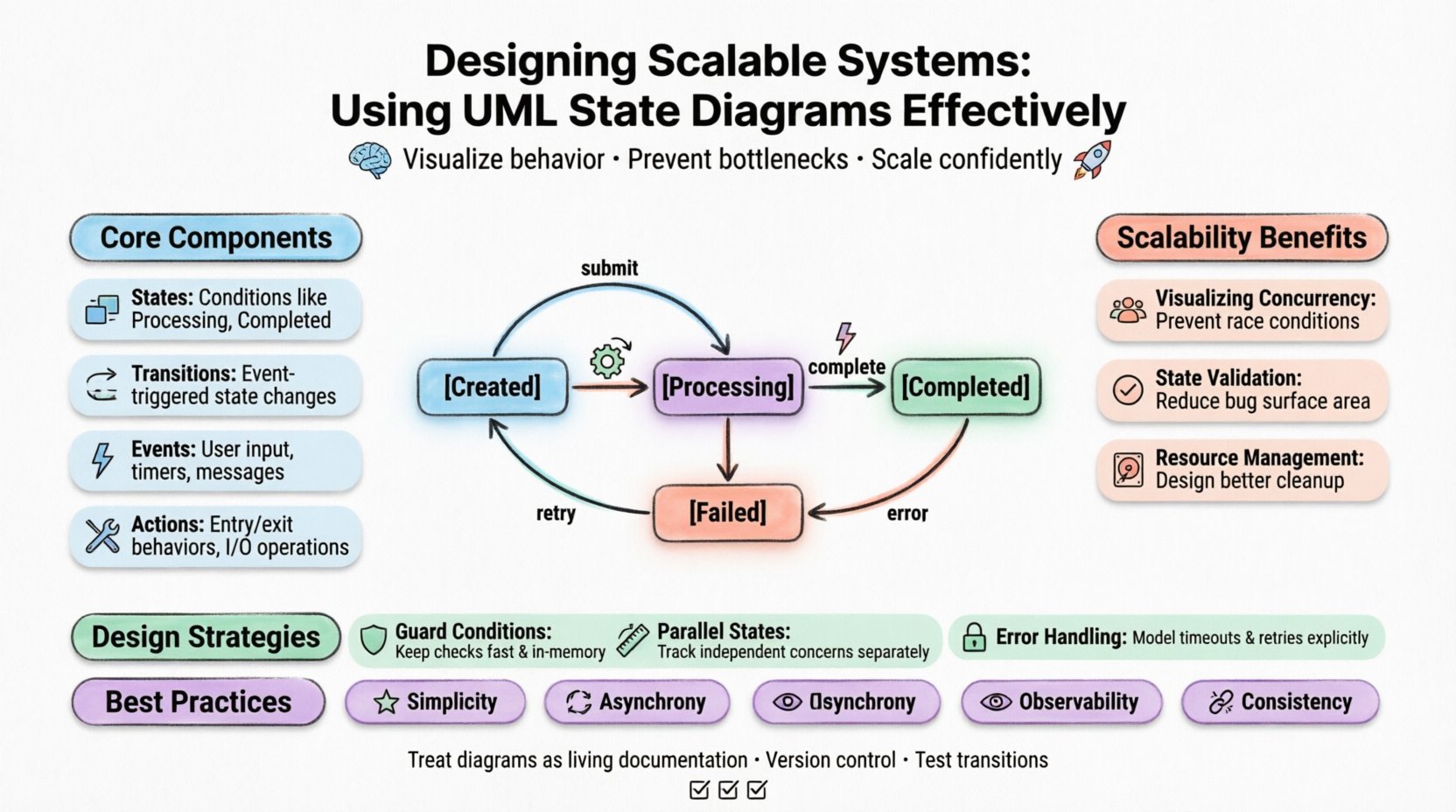
- Visualizing Concurrency: They reveal how multiple threads or processes interact with the same object. This prevents race conditions that crash systems under high load.
- State Validation: They ensure that operations are only allowed in valid states. This reduces the surface area for bugs that cause data corruption.
- Resource Management: They highlight states where resources are held, allowing architects to design better cleanup protocols.
Core Components of a State Diagram 🧩
To use these diagrams effectively, one must understand the building blocks. Every diagram consists of specific elements that define the rules of interaction. Misinterpreting these elements leads to flawed designs.
1. States 🟦
A state represents a condition during which an object meets certain criteria. In a scalable system, states often correspond to resource allocations. For example, an order processing service might have states like Processing, Paused, Completed, or Failed. Each state dictates what actions are permissible.
When designing for scale, avoid creating too many granular states. Excessive states increase the complexity of the transition logic. Keep states high-level enough to cover common scenarios, but specific enough to enforce business rules.
2. Transitions 🔄
A transition is the change from one state to another. It is triggered by an event. In a distributed system, events often come from external sources, such as user inputs, timer expirations, or messages from other services.
For scalability, transition logic must be lightweight. Heavy computations inside a transition can block the event loop. The diagram should show where processing happens versus where simple state changes occur.
3. Events ⚡
Events are the triggers that cause transitions. They can be signals, messages, or time-based occurrences. In a high-throughput environment, the volume of events is significant. The state machine must handle event queues efficiently.
4. Actions 🛠️
Actions are behaviors executed during a transition or while in a state. They include entry actions, exit actions, and do activities. In scalable architectures, actions often involve I/O operations or database writes.
| Component | Definition | Scalability Impact |
|---|---|---|
| State | Condition of the object | Determines resource locking requirements |
| Transition | Change from state A to B | Affects latency and throughput |
| Event | Trigger for change | Influences queue management and concurrency |
| Action | Behavior during transition/state | Impacts CPU and I/O usage |
Designing for Concurrency and Scalability 🚀
When a system scales, it handles multiple requests simultaneously. A single object instance might be accessed by multiple threads. This introduces the risk of inconsistent states. State diagrams help design mechanisms to handle this safely.
Handling Concurrent Access 🔒
If a state machine allows a transition while a previous one is still executing, data integrity is at risk. The diagram should clearly show if a state is exclusive. For example, a Writing state might prevent any other Reading transitions until the write is complete.
Architects often implement locking mechanisms based on the state diagram. If the diagram shows multiple parallel paths, the implementation must support parallel execution without state corruption.
Managing Event Queues 📥
Under high load, events may arrive faster than they can be processed. The state machine needs a buffer. The diagram helps identify where this buffering is necessary. States that involve long-running processes should have clear timeouts.
Consider the flow of events:
- Synchronous Events: These block the caller until the transition is complete. Avoid these in high-traffic areas.
- Asynchronous Events: These allow the system to acknowledge receipt and process later. This is preferred for scalable designs.
- Internal Events: Events that trigger transitions without external interaction. These are useful for internal housekeeping.
Transition Management Strategies 🔄
Transitions are the lifeblood of a state machine. Poorly designed transitions lead to bottlenecks. Here are strategies to manage them effectively.
Guard Conditions 🛡️
Guard conditions are boolean expressions that must be true for a transition to occur. They add logic to the flow. In scalable systems, guard conditions should be fast to evaluate. If a guard condition requires a database query, it becomes a performance bottleneck.
Best Practice:
- Keep guard conditions in memory whenever possible.
- Prefer simple checks over complex calculations.
- Cache the results of expensive checks if they do not change frequently.
Parallel States (Orthogonal States) 📐
Complex systems often need to track multiple independent aspects of behavior simultaneously. For example, a user session might track Authentication Status and Subscription Status independently. Using orthogonal states allows the diagram to represent this concurrency clearly.
This reduces the combinatorial explosion of states. Instead of creating separate states for every combination (e.g., Authed_Subscribed, Authed_Unsubscribed, Unauthed_Subscribed), you define separate regions for each concern. This simplifies the logic and makes the system easier to extend.
Common Pitfalls and How to Avoid Them 🚫
Even experienced architects make mistakes when modeling. These pitfalls can undermine scalability efforts. Recognizing them early prevents costly refactoring later.
Pitfall 1: The Spaghetti State Machine 🍝
A state machine with too many transitions between states becomes difficult to maintain. This is often called a “spaghetti diagram.” It is hard to trace the flow of logic.
Solution: Use hierarchical states. Group related states into superstates. This reduces the number of transitions needed to connect them. It also improves readability.
Pitfall 2: Ignoring Error States 📉
Many diagrams only show the happy path. They omit what happens when things go wrong. In a scalable system, failures are expected. Ignoring them leads to deadlocks.
Solution: Explicitly model error recovery states. Define what happens when a transition fails. Include timeouts and retry logic in the diagram.
Pitfall 3: State Explosion 💥
As the system grows, the number of states can become unmanageable. This happens when states are too granular or when there are too many variables.
Solution: Consolidate states where possible. Use variables to track data within a state rather than creating new states for every variation. For instance, instead of states Order1, Order2, Order3, use a single OrderProcessing state with a variable for the current step.
Integration with System Architecture 🏛️
A state diagram does not exist in isolation. It must integrate with the broader system architecture. This includes how the state machine interacts with databases, caches, and external services.
Persistence Strategy 💾
For long-running processes, the state must be persisted. If the system restarts, it should resume from the last known state. The diagram helps define the persistence points.
Consider these options:
- Memory Only: Fast, but state is lost on restart. Good for ephemeral tasks.
- Database Storage: Durable, but adds latency. Good for critical transactions.
- Cache Storage: Fast and durable within a cluster. Good for high-throughput sessions.
Event Sourcing Compatibility 📝
Some architectures use event sourcing, where state is derived from a log of events. State diagrams complement this by showing how the log is processed. The diagram defines the rules for applying events to the current state.
This approach ensures that the state machine is auditable. You can replay events to rebuild the state, which is valuable for debugging and scaling.
Best Practices for Maintenance 🛠️
Once the system is live, the state machine will evolve. Requirements change, and new features are added. Maintaining the diagram and the code is essential.
Version Control for Models 📂
Treat state diagrams as code. Store them in version control systems. This allows you to track changes, compare versions, and revert if necessary. It also facilitates collaboration among team members.
Automated Testing 🧪
State machines are deterministic. This makes them ideal for automated testing. Write tests that verify every transition.
- Unit Tests: Verify that a specific event triggers the correct transition.
- Integration Tests: Verify that the state machine interacts correctly with the database and external services.
- Load Tests: Verify that the state machine handles high volumes of events without performance degradation.
Documentation Updates 📖
When code changes, the diagram must be updated. An outdated diagram is worse than no diagram because it misleads developers. Establish a rule that code changes require diagram updates.
Summary of Design Principles 📝
To ensure your state diagrams support scalability, adhere to these core principles:
- Simplicity: Keep states and transitions minimal. Complexity kills scalability.
- Asynchrony: Favor asynchronous event handling to decouple components.
- Error Handling: Model failure paths explicitly. They are part of the lifecycle.
- Observability: Design states that emit clear logs for monitoring.
- Consistency: Ensure that state transitions maintain data consistency across distributed nodes.
Final Thoughts on Implementation 🏁
Using UML State Diagrams effectively is not about drawing pretty pictures. It is about rigorous thinking. It forces you to confront the behavior of your system before writing a single line of code. When done correctly, it provides a blueprint that guides the development of resilient, scalable applications.
Start small. Model the core behavior of a single component. Refine the diagram as you understand the system better. Use it as a living document that evolves with your architecture. By prioritizing clear state management, you build systems that can withstand the demands of growth. 🌱
Remember, the goal is stability. A well-modeled state machine ensures that your system behaves predictably, even when the load increases dramatically. This predictability is the foundation of true scalability.