
Designing complex systems requires more than just drawing boxes and lines. It demands a deep understanding of behavior over time. The UML State Machine Diagram offers a powerful way to model how objects change state in response to events. However, drawing a diagram is only the first step. The real value lies in recognizing patterns within those diagrams. By identifying reusable structures, architects and developers can reduce complexity and improve maintainability.
This guide explores the core patterns found in state machine modeling. We will examine how to spot recurring behaviors and convert them into standard components. This approach streamlines the design process and ensures consistency across different parts of a system.
🧩 Fundamentals of State Machine Modeling
Before diving into patterns, it is essential to establish a baseline understanding of the components involved. A state machine diagram represents the dynamic behavior of an object. It focuses on the sequence of states an object passes through during its lifecycle.
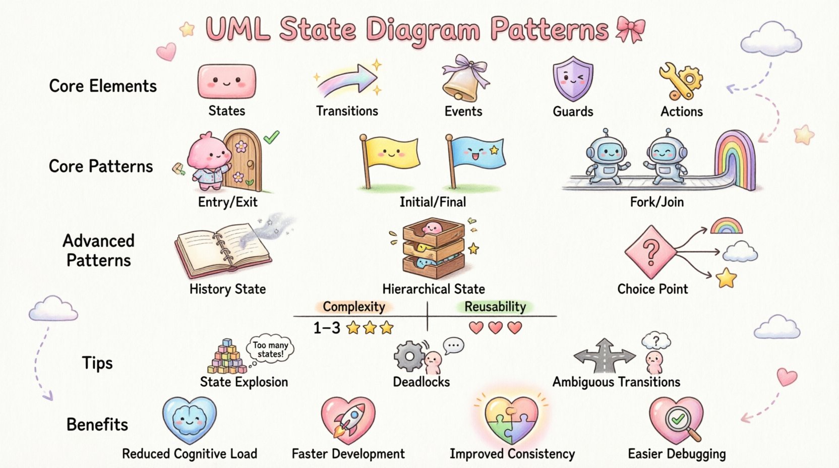
Core Elements
- States: Conditions or situations during which an object waits for events. These are represented by rounded rectangles.
- Transitions: The link between states. They indicate how an object moves from one condition to another.
- Events: Signals that trigger a transition. These can be method calls, messages, or time-based triggers.
- Guards: Boolean conditions that must be true for a transition to occur. They are written in square brackets.
- Actions: Activities performed during the entry, exit, or during a transition.
Understanding these elements is crucial for pattern recognition. Patterns often emerge from specific combinations of these components working together.
🔄 Core Structural Patterns
Certain structural arrangements appear frequently across various system domains. Recognizing these allows you to apply known solutions rather than reinventing the wheel.
1. The Entry-Exit Lifecycle Pattern
Every state in a robust model typically has entry and exit behaviors. This pattern ensures that resources are managed correctly when an object enters or leaves a condition.
- Entry Action: Code or logic that runs immediately upon entering the state. Common uses include initializing variables, opening files, or starting timers.
- Exit Action: Code or logic that runs immediately before leaving the state. Common uses include saving data, closing connections, or cleaning up resources.
Reusability Factor: High. This pattern is universal across almost every state machine. It should be standardized in your modeling guidelines.
2. The Initial and Final State Pattern
Every valid state machine must have a clear starting point and a clear ending point. This provides a definitive boundary for the object’s lifecycle.
- Initial State: A solid black circle. It marks where the object begins its existence.
- Final State: A solid black circle inside a larger circle. It marks where the object ceases to exist or becomes inactive.
Reusability Factor: Mandatory. While the specific initial transitions differ, the existence of these anchors is a requirement for valid models.
3. The Fork and Join Pattern
Complex systems often need to perform multiple actions simultaneously or wait for multiple conditions to be met. This pattern handles concurrency.
- Fork: A single transition splits into multiple concurrent paths. This indicates that multiple activities start at the same time.
- Join: Multiple concurrent paths merge into a single path. This indicates that the system waits for all concurrent activities to complete before proceeding.
Reusability Factor: Medium to High. While the logic varies, the structure of parallel processing is a standard architectural pattern.
🧠 Advanced Behavioral Patterns
As systems grow in complexity, simple linear flows are insufficient. Advanced patterns handle history, hierarchy, and conditional branching.
4. The History State Pattern
One of the most powerful tools for reusability is the History State. It allows a composite state to remember its previous sub-state.
- Shallow History: Indicates the last sub-state visited at the top level of a composite state.
- Deep History: Indicates the last nested sub-state visited, regardless of depth.
Use Case: Imagine a user session. If a user is interrupted while filling out a form and returns later, the system should return them to the exact field they were editing, not the beginning of the form.
Reusability Factor: High. This pattern is essential for maintaining context in interactive applications.
5. The Hierarchical State Pattern
Also known as Composite States, this pattern allows states to contain other states. This reduces diagram clutter and improves modularity.
- Internal States: States contained within a parent state.
- Transition Scope: Transitions can occur between internal states without leaving the parent state.
- Propagation: Events can be handled at the parent level if no child state handles them.
Reusability Factor: Very High. Hierarchical structures are the backbone of scalable system design. A pattern defined at a high level can be reused across multiple modules.
6. The Choice Point Pattern
Not all transitions lead to a single next state. Sometimes, the next step depends on a complex condition. A Choice Point uses a diamond shape to represent a decision.
- Decision Logic: Multiple outgoing transitions are guarded by different conditions.
- Flow Control: This mimics
if-elselogic within the state machine.
Reusability Factor: Medium. While the logic is unique to the domain, the structural representation is consistent.
📊 Comparing Common Patterns
To aid in recognition, here is a comparison of the most frequent patterns found in state machine diagrams.
| Pattern Name | Primary Function | Complexity | Reusability |
|---|---|---|---|
| Entry/Exit | Resource Management | Low | Very High |
| Fork/Join | Concurrency | High | High |
| History State | Context Preservation | Medium | High |
| Composite State | Abstraction | Medium | Very High |
| Choice Point | Conditional Branching | Medium | Medium |
🔎 Identifying Reusable Structures
Recognizing a pattern is one thing; extracting it for reuse is another. This section outlines the methodology for identifying structures that can be standardized.
Step 1: Analyze Behavioral Consistency
Look for states or transitions that appear in multiple diagrams. If a “Processing” state always triggers a “Validation” event, that is a candidate for a reusable component.
- Check for identical event sequences.
- Check for identical entry/exit actions.
- Check for identical guard conditions.
Step 2: Evaluate Scope and Dependency
A reusable structure should not be too tightly coupled to specific implementation details. It must be abstract enough to fit into different contexts.
- High Coupling: Hardcoded values or specific database schemas. Not reusable.
- Low Coupling: Parameterized events or generic resource handlers. Reusable.
Step 3: Document the Intent
When you identify a pattern, document why it exists. This ensures that future modelers understand the behavior without needing to reverse-engineer the logic.
- Define the trigger conditions clearly.
- Define the expected outcome.
- Note any exceptions or edge cases.
⚠️ Common Pitfalls in State Modeling
Even with patterns, errors occur. Being aware of common mistakes helps in maintaining the integrity of the state machine.
1. State Explosion
This occurs when a single state machine tries to manage too many distinct conditions. The diagram becomes unmanageable and difficult to read.
- Solution: Use Hierarchical States to break down complexity.
- Solution: Apply the Composite State pattern to group related behaviors.
2. Deadlocks
A deadlock happens when a state has no outgoing transitions for a specific event, or when the system reaches a state where no further progress is possible.
- Solution: Ensure every state has a defined path for expected events.
- Solution: Implement an Invalid Event transition that handles unexpected inputs gracefully.
3. Ambiguous Transitions
Confusion arises when multiple transitions from a state have the same event and guard condition. The system cannot determine which path to take.
- Solution: Ensure guard conditions are mutually exclusive.
- Solution: Use explicit choice points to clarify decision logic.
🛠️ Implementation Strategy
Once patterns are identified, the next step is integration into the development lifecycle. This ensures that the design translates effectively into code.
1. Standardize Naming Conventions
Consistent naming makes patterns easier to spot. Use prefixes or suffixes to indicate state types.
- State Names: Use nouns (e.g.,
IdleState,ProcessingState). - Event Names: Use verbs (e.g.,
StartProcessing,CompleteTask). - Transition Names: Descriptive (e.g.,
OnSuccessTransition).
2. Leverage Behavioral Templates
Many modeling environments support templates. Create a library of verified state patterns.
- Store standard Entry/Exit blocks.
- Store standard Error Handling loops.
- Store standard Timeout mechanisms.
3. Review and Refine
State machines evolve. Regular reviews ensure that patterns remain valid as requirements change.
- Schedule periodic audits of state diagrams.
- Check for deprecated states.
- Verify that guards still match business logic.
🌐 Benefits of Pattern Recognition
Adopting a pattern-based approach yields tangible benefits for the organization and the development team.
- Reduced Cognitive Load: Developers do not need to understand the logic from scratch. They recognize the pattern.
- Faster Development: Reusing proven structures speeds up the coding phase.
- Improved Consistency: Systems behave predictably because they use standard patterns.
- Easier Debugging: When a pattern is broken, the fix is often known and documented.
📝 Summary of Key Takeaways
Building effective state machine diagrams requires more than just drawing lines. It requires an eye for structure and behavior. By focusing on the core patterns discussed—Entry/Exit, History, Hierarchy, and Fork/Join—you can create models that are both robust and maintainable.
Remember that reusability is about abstraction. The goal is to create structures that solve problems without being tied to a single implementation. Use the table provided to quickly reference which pattern fits your specific needs. Avoid common pitfalls like state explosion and deadlocks by planning your hierarchy carefully.
Finally, treat your state diagrams as living documentation. As the system evolves, the patterns should evolve with it. Regular review ensures that the models remain accurate representations of the system’s behavior over time.
By applying these principles, you move beyond simple diagramming to true architectural design. The result is a system that is easier to understand, easier to build, and easier to maintain.


")