
Building robust backend systems requires clear communication between components. When services interact, the flow of data determines stability and performance. Sequence diagrams provide a visual language to map these interactions. They are not just drawings; they are contracts of behavior. In modern architectures, where requests often do not wait for immediate responses, understanding asynchronous interactions is critical. This guide explores how to model these flows accurately, ensuring your system design remains clear under pressure.
🧩 The Anatomy of Communication
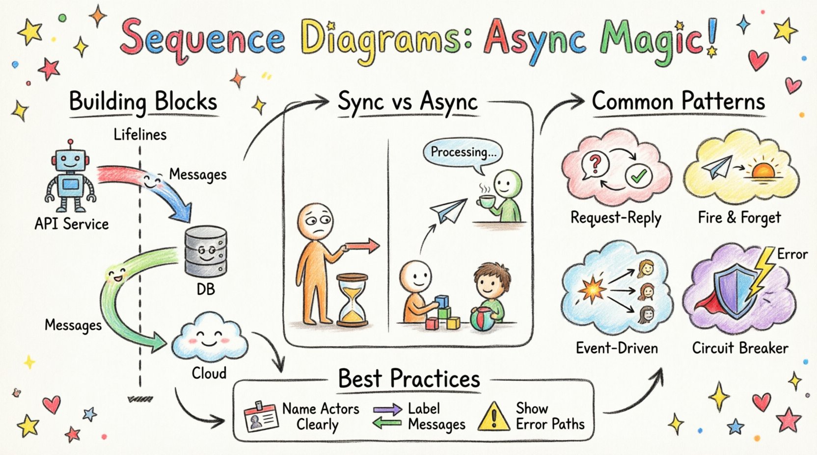
Before mapping complex flows, one must understand the building blocks. A sequence diagram represents time moving downwards. Each vertical line represents an object or a service. These lines are called lifelines. They show the existence of an entity throughout the interaction. The horizontal arrows represent messages passing between these entities.
- Lifelines: Vertical dashed lines representing participants like controllers, services, or databases.
- Activation Bars: Rectangles on the lifeline indicating when an object is active and processing a task.
- Messages: Arrows indicating the transfer of data or control. They can be synchronous or asynchronous.
- Return Messages: Dashed arrows showing the response flowing back to the caller.
When designing backend systems, every arrow represents a network call, a database query, or an internal function invocation. Precision here prevents logical errors later. If a diagram shows a message leaving a lifeline without a corresponding return, it implies a specific handling strategy, such as fire-and-forget.
🔄 Synchronous vs. Asynchronous Flows
Distinguishing between synchronous and asynchronous behavior is the core of this discussion. In a synchronous flow, the sender waits for the receiver to finish before continuing. This creates a blocking state. In an asynchronous flow, the sender dispatches a message and continues its own work immediately. The receiver processes the task independently.
| Feature | Synchronous Interaction | Asynchronous Interaction |
|---|---|---|
| Blocking | Yes, caller pauses | No, caller continues |
| Visual Marker | Solid arrow | Open (hollow) arrow |
| Response | Immediate return arrow | Deferred or separate event |
| Use Case | Quick lookups, transactions | Notifications, background jobs |
Visualizing this difference is vital for system architects. A solid arrow implies a stack depth increase. An open arrow implies a queue entry. Confusing these two can lead to performance bottlenecks where a fast service is held up by a slow downstream dependency.
⚡ Visualizing Asynchronous Flow
When modeling async interactions, the diagram must clearly indicate that the sender does not wait. The message arrow typically uses an open arrowhead. The return message, if it exists, appears much later in the sequence. It might not even return to the original sender.
Consider a scenario where a user submits a form. The backend receives the request and acknowledges it instantly. However, the actual processing happens later. In the diagram:
- The User sends a request to the API Gateway.
- The Gateway sends a message to the Queue Service.
- The Gateway immediately returns a 202 Accepted status to the User.
- The Queue Service sends a message to the Worker Service.
- The Worker Service sends a message to the Database.
- The Worker Service sends a notification to the User.
Notice the timeline. The User is not waiting for the Database. This decoupling is a hallmark of resilient systems. The diagram makes this temporal gap visible. Without it, developers might assume the database write happens before the response is sent.
🏗️ Common Backend Patterns
Certain patterns emerge frequently when modeling backend logic. Recognizing them helps in standardizing diagrams across teams.
1. Request-Reply
This is the standard web request. The client sends data and expects a result. While often synchronous, it can be async if the response is delivered via a separate channel later.
2. Fire and Forget
The sender transmits data and performs no further action. There is no return message. This is common for logging or analytics events. The diagram shows the arrow ending at the receiver without a return path.
3. Event-Driven
Multiple services react to a single event. One source publishes a change. Multiple subscribers listen. This creates a fan-out pattern. The diagram shows one arrow branching into multiple lifelines.
4. Circuit Breaker
p>When a downstream service fails, the caller stops sending requests to prevent cascade failure. In a diagram, this is shown as a decision point. If the service is down, the arrow leads to an error handler instead of the target service.
| Pattern | Message Style | Key Diagram Element |
|---|---|---|
| Request-Reply | Solid Arrow + Dashed Return | Combined Activation |
| Fire and Forget | Open Arrow | No Return Line |
| Event-Driven | Multiple Open Arrows | Fan-out Branching |
| Circuit Breaker | Conditional Arrows | Decision Nodes |
🧠 Handling Concurrency & State
Backend systems are rarely single-threaded. Concurrency introduces complexity. A sequence diagram captures the logical order, but it must also hint at state management. When multiple threads process the same data, race conditions occur. Diagrams help identify where locks or transactions are needed.
- Transaction Boundaries: Highlight sections where a database transaction must encompass multiple calls. Use combined fragments to group these steps.
- Locking: Indicate if a resource is locked during a specific interaction. This prevents other threads from modifying the data simultaneously.
- Idempotency: Show that a message might be sent multiple times. The receiver must handle duplicates without side effects.
Consider a payment system. If two requests arrive for the same order, the diagram should show a check for order status before processing. If the status is already “paid”, the second request should be rejected. This logic belongs in the sequence flow.
🔍 Debugging Complex Flows
When diagrams become complex, readability suffers. Teams often struggle to trace the path of a request. To avoid this, use grouping mechanisms. These allow you to encapsulate specific behaviors.
- Alt (Alternative): Use this for conditional logic. For example, “If Auth Passes, Proceed; Else, Return Error”.
- Opt (Optional): Use this when a step might not happen. For example, “If User Exists, Send Welcome Email”.
- Loop: Use this for repetitive actions, such as processing a list of items.
- Break: Use this to show a failure condition where the normal flow stops.
These fragments keep the main timeline clean. They prevent the diagram from becoming a tangled web of arrows. Each fragment represents a logical block of code. This alignment between diagram and code is essential for maintainability.
📈 Best Practices for Clarity
Creating a diagram is an act of communication. It must be understood by developers, testers, and stakeholders. Follow these principles to ensure clarity.
- Keep it Focused: Do not diagram every single function call. Focus on the critical path and the exceptions.
- Name Actors Clearly: Use names that reflect their role, such as “Order Service” or “Payment Gateway”, rather than generic terms like “Object A”.
- Label Messages: Every arrow should have a name. Describe the action, such as “Create Invoice” or “Validate Token”.
- Use Consistent Styles: Ensure all teams use the same arrow types for sync vs. async. Consistency reduces cognitive load.
- Time is Relative: Remember that the vertical distance does not always represent real time. It represents logical sequence. A long gap might mean a long wait, or it might just mean a complex calculation.
🛠️ Documentation Lifecycle
A sequence diagram is not a static artifact. It evolves with the code. When a new feature is added, the diagram should be updated. When a service is decomposed, the lifelines change. Maintaining this document ensures that the architecture remains understood over time.
Integrate diagram updates into the pull request process. When a developer changes the interaction logic, they should update the diagram as part of the commit. This practice keeps the documentation in sync with the implementation. It prevents the drift that occurs when code changes but docs do not.
⚠️ Common Pitfalls
Even experienced engineers make mistakes when modeling these systems. Be aware of common traps.
- Assuming Order: Just because one arrow appears above another does not mean it happens before in real time. In async systems, messages can arrive out of order.
- Ignoring Errors: Only showing the happy path gives a false sense of security. Always map out error handling and timeouts.
- Too Much Detail: Including every variable passed between services makes the diagram unreadable. Focus on the control flow, not the data payload.
- Missing Timeouts: In async systems, waiting forever is a risk. Indicate where timeouts occur in the diagram to show resilience strategies.
🔗 Integrating with Logs
Sequence diagrams bridge the gap between design and observation. When you add logging to your backend, the log trace should match the diagram. If the diagram shows Service A calling Service B, the logs should show that sequence. This alignment makes debugging production issues much faster. You can visualize the actual flow against the intended design.
Use correlation IDs to link logs across services. This allows you to reconstruct the sequence diagram from the logs of a specific request. This capability turns the diagram into a living reference for incident response.
🚀 Final Thoughts
Modeling asynchronous interactions requires discipline. It forces you to think about time, order, and failure. A well-drawn sequence diagram acts as a blueprint for reliability. It helps teams agree on how data moves through the system. By following these guidelines, you ensure that your backend architecture is not just functional, but understandable.
Start with the critical paths. Add the exceptions. Refine the notation. Over time, these diagrams become a shared language for your engineering team. They reduce ambiguity and accelerate development. In a complex environment, clarity is the most valuable asset you can provide.